Hi... with regard to the isolation... a good test is to apply a squarewave at around 3 khz or so and with the amp on FULL volume and your ear up to the speaker see if any breakthrough occurs. I can apply 20 volts peak to peak (max my function generator gives) with zero breakthrough. You certainly couldn't measure it as it is below the noise floor. That is an extremely severe test.
Depending on the relay design you may still experience breakthrough at HF due to capacitive effects.
As you know , greater capacitive coupling appears in silicon than in vacuum / air !
As you know , greater capacitive coupling appears in silicon than in vacuum / air !
Hi... I'm not disputing that 🙂 If you re read all my comments I keep referring to a series shunt arrangement for silicon vs a single relay contact... which is what most use when using relays.
The silicon working into a virtual earth will outperform the relay every time with around -120db attenuation at 10khz or so.
For analogue switching you can't beat this. The FET's are at the input to a virtual earth amp and so see no signal across them. The isolation is far better than any switch or relay... and that is something those 4066 are poor for, due to that stray capacitance etc. The second opamp is just to maintain correct phase.
And this lends itself to full remote control too.
this looks nice and simple but I'm afraid I don't understand it. What does it mean x and y driven in antiphase? How is the signal switched (is there a button or switch)? How many channels can it handle? The pic is also very low res and hard to read. Looks like a promising design though.
Hi...
OK... it switches as many inputs as you want. Each input repeats the circuit shown in the square and the FET's source's all common together on pin 2 of the opamp. A mixer in other words...
X and Y in antiphase. That means that as one goes high the other goes low, except that here the levels are high = 0.3 volts and low = -8 volts. So as the series FET is on passing the signal the shunt FET is fully off and vise versa. I used a PIC micro and logic decoder to give full remote control, along with a normal rotary switch on the front for manual control if needed (remote not working or handy etc)
You can see the FET's here all in a row near the input sockets, post #286 and 287
http://www.diyaudio.com/forums/solid-state/96192-post-your-solid-state-pics-here-15.html
http://www.diyaudio.com/forums/solid-state/96192-post-your-solid-state-pics-here-15.html
I keep referring to a series shunt arrangement for silicon vs a single relay contact... which is what most use when using relays.
IF you have a double-pole relay (as many are), you could wire it in the same manner as the FET circuit, which I suspect would perform even better. However, top-end signal-quality relays go for about $100 to $200 EACH, and a FET is around 25c.
I would really love to build a 4-channel switch for my audio project using the previously mentioned MAX4709. I'm interested in this if it is less noise/distortion than simply using small DPDT switches. I would also like to have a switch that uses a single button to select each source.
I found this:
http://www.electronicsforu.com/efylinux/circuit/feb2003/Add on stereo channel selector.pdf
which looks very interesting but I'd like to use the much easier to find LM3914 instead of the KA2281 in that shem. Or better yet, omit it completely for a simpler circuit. I'm also curious what kind of distortion it might have. I've searched around the net a LOT but haven't found much (very little on ESP pages too). Anyone know a good schem for this kind of a circuit?
Can anyone comment on this circuit? I found an equivalent to the KA2281/LM3914 with opamps (see attached schem) and it seems using a MAX4709 should produce a very decent low-noise button select with this circuit. Any suggestions? This looks like it could be a really fine circuit.
Attachments
I am interested in building a audio inputs switch (audio selector). I have experience in digital circuits, but not much in analog circuits, but I am passionate about audio. So I need a little help.
Had thought of using a pair of 4051 with 8 inputs each, and also a small micro controller (atmel avr or microchip pic). It would be better to use the 4052? (I prefer to have 8 stereo inputs with two 4051, one for each channel)
Someone can recommend me any design or schematic?
I have to put a "audio buffer" or preamp? in the output? in the input? in two places? (if so, could use a NE5532?)
Any information is welcome: schematics, designs, tips, ideas... (I need help especially in the analog audio part (input or output preamplifier, buffer...)
Thanks you very much for everything!
PS: The 4051 has an acceptable quality? or make noise in the audio?
Thanks! bye!
CD405x switches have some significant non-linearities in 'voltage' mode where you simply run a few volts P-P in and get the same level out but if you use them in 'current' mode where the switch out goes to the '-' input of an opamp running as a transimpedance amplifier you can get very good performance as you've reduced the signal ampitude to well under the voltage non-learity point. Of course you want a small value resistor between to opamp input and mux output to reduce the capacitance on the '-' input node. This will also reduce the overload issue on the input being selected but you can still cause protection diode currents on unused inputs _unless_ you add some smart loading circuits to shunt not-selected inputs to ground. You'd probably want a microcontroller to handle the logic though it certainly could be done with TTL or GALs. Parts count can be very low with a uProc with powerful user insterface / remote controls.
G²
As stratus46 says, use in a virtual earth arrangement to overcome the nonlinearities of the CMOS switches. That means using in a circuit like in post #15 Use the switches to replace the FET's.
If you are into PIC programming have a look at this...
FPRC5RX - DIY learning IR decoder
not quite what you are asking for but one of the most flexible designs I have seen and it works exactly as described.
If you are into PIC programming have a look at this...
FPRC5RX - DIY learning IR decoder
not quite what you are asking for but one of the most flexible designs I have seen and it works exactly as described.
I used HEF405X Series analog multiplexer/demultiplexers in several applications...
HEF 405X series gives 5 nano seconds propogation delay and % 0,04 distortion under 10V supply voltage.Please be realistic... Hi-Fi systems are gives us about %0.1 distortion.Be easy and use these products.
You are talking about relays for signal switching.What about RFI and EMI conditions generated by relay coil ?? .This gives a chattering on sound while switching i think..
Take a look at these links:
Detailed Datasheet (Philips)
http://ics.nxp.com/products/hef/datasheet/hef4052b.pdf
Some applications
Audio Switch Notes
MOSFET Integrated Amplifier
Last edited:
Urgent Digital Control
You Quoted:-
" I used HEF405X Series analog multiplexer/demultiplexers in several applications...
HEF 405X series gives 5 nano seconds propogation delay and % 0,04 distortion under 10V supply voltage.Please be realistic... Hi-Fi systems are gives us about %0.1 distortion.Be easy and use these products.
You are talking about relays for signal switching.What about RFI and EMI conditions generated by relay coil ?? .This gives a chattering on sound while switching i think..
Take a look at these links:
Detailed Datasheet (Philips)
http://ics.nxp.com/products/hef/datasheet/hef4052b.pdf
Some applications
Audio Switch Notes
MOSFET Integrated Amplifier"
I want to know can these 405X Series can Control analog singnals of 18V P-p that is VEE=-9V and VDD=9V with Digital Control Signals of 5V? Is there any way out? Please do reply at the earliest. Thanking you in advance.
I used HEF405X Series analog multiplexer/demultiplexers in several applications...
HEF 405X series gives 5 nano seconds propogation delay and % 0,04 distortion under 10V supply voltage.Please be realistic... Hi-Fi systems are gives us about %0.1 distortion.Be easy and use these products.
You are talking about relays for signal switching.What about RFI and EMI conditions generated by relay coil ?? .This gives a chattering on sound while switching i think..
Take a look at these links:
Detailed Datasheet (Philips)
http://ics.nxp.com/products/hef/datasheet/hef4052b.pdf
Some applications
Audio Switch Notes
MOSFET Integrated Amplifier
What EMI what RFI ??
When i select an input , that is : the relay is on and nothing more come from , as from basic physics we know that !
And about a simple Ag contact what distortion introduce in audio path ???
I want to know can these 405X Series can Control analog singnals of 18V P-p that is VEE=-9V and VDD=9V with Digital Control Signals of 5V? Is there any way out? Please do reply at the earliest. Thanking you in advance.
Yes... use a level shift arrangement using perhaps a small signal FET ( eg 2n7000) The logic runs on 0 and 5 volt, so assuming 0 is the same as audio ground use the FET and high value resistor across the -/+9 vdc and use a high value resistive level shift divider from the logic to the gate of FET.
Or run the logic referenced to -9 volts... loads of possibilities.
Yes it's possible.Please look at this sch.
http://www.sydzdiy.com/uploads/allimg/090818/0040492I4-0.jpg
http://www.sydzdiy.com/uploads/allimg/090818/0040492I4-0.jpg
Please Urgent
Respected Sir,
Thank you for the help but still one confusion, in the pic A, B are controlled by 6 - 12V Logic levels, right? Can the chip series be operated at +12 to -12V and controlled by 5V Logic Levels? Will there be no problem? Then why it is not mentioned in the datasheet? Rather it is written Logic 1 is equal to VDD? Thanking in advance for your help.
I am interested in building a audio inputs switch (audio selector). I have experience in digital circuits, but not much in analog circuits, but I am passionate about audio. So I need a little help.
Had thought of using a pair of 4051 with 8 inputs each, and also a small micro controller (atmel avr or microchip pic). It would be better to use the 4052? (I prefer to have 8 stereo inputs with two 4051, one for each channel)
Someone can recommend me any design or schematic?
I have to put a "audio buffer" or preamp? in the output? in the input? in two places? (if so, could use a NE5532?)
Any information is welcome: schematics, designs, tips, ideas... (I need help especially in the analog audio part (input or output preamplifier, buffer...)
Thanks you very much for everything!
PS: The 4051 has an acceptable quality? or make noise in the audio?
Thanks! bye!
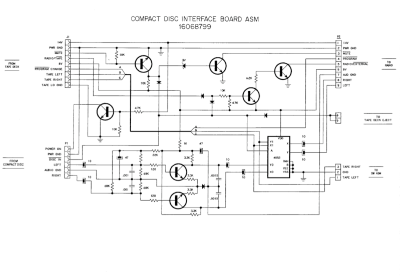
Here is a sample 4052 used as a tape/cd interface circuit for AC DELCO car stereo.
I have been studying this rather old thread, but being quite unexperienced in analog design, I still have two questions.
First, what I would like to achieve:
I want to connect one of 6 sources (tuner, CD-player, record player, TV-receiver with optical digital output plus adapter optical to cinch, USB sound card connected to a Raspberry PI, tape recorder) to the input of a stereo amplifier.
Currently I use a rotary switch for this purpose.
I would like to use instead of the rotary switch two CD74HC4051-EP multiplexers (one per stereo channel) controlled by a Raspberry Pico microcontroller. Advantages: I could control the selection of the source signal remotely via a 433 MHz receiver, or time based,e.g., radio during the day, TV in the evening.
Now my questions:
Are the audio signals always positive, i.e., some positive voltage V +- a, with a < V, or is the signal symmetric to 0?
May I connect the inputs of the multiplexer directly with my signal sources and the output directly with my receiver?
If not, why not?
Now my questions:
Are the audio signals always positive, i.e., some positive voltage V +- a, with a < V, or is the signal symmetric to 0?
As output from a source component (CD player, Tuner etc) they are always signals centred around 0 volts (ground) meaning they swing above and below ground. A sine wave would be symmetrical to 0v, audio signals by their nature are asymmetric but will average out to zero over time.
Once applied to a piece of equipment like a preamp the signal may or may not then continue in that form. For example if the equipment runs on a single positive 20 volt rail then the audio signal will be superimposed onto some DC voltage within the 0 to 20 volts DC range. To do this would require an input coupling capacitor to block the DC from the equipment affecting the source component.
May I connect the inputs of the multiplexer directly with my signal sources and the output directly with my receiver?
If not, why not?
Essentially yes but you should design so that unused inputs are not floating. They should present a defined impedance if open and also think of AC coupling them as well as a safeguard. A lot depends on how you power the multiplexor i.e. single or dual rail. If single rail then it needs to be suitably biased to a half supply point. Single rail makes AC coupling essential.
The output of the multiplexor will be either zero volts DC (dual rail) or half supply (single rail) and that must be accounted for when connecting to the next stage.
Thanks a lot for your reply! Concerning the input signals, I was confused by wikipedia. They state (under Audiosignal)
in the german version only:
Ein Audiosignal (auch Tonsignal) ist elektrisch gesehen ein pulsierender Gleichstrom
My translation: an audio signal is a pulsating direct current.
So they seem to be wrong.
Between record player and amplifier there is a preamplifier. Will that shift the signal? Can I find out by attaching a DC voltmeter and a capacitor in parallel?
As the multiplexer can be used with two power voltages, -5 V and +5 V, it seems easy to deal with a symmetric signal.
You say:
You also say:
Thanks for your help!
in the german version only:
Ein Audiosignal (auch Tonsignal) ist elektrisch gesehen ein pulsierender Gleichstrom
My translation: an audio signal is a pulsating direct current.
So they seem to be wrong.
Between record player and amplifier there is a preamplifier. Will that shift the signal? Can I find out by attaching a DC voltmeter and a capacitor in parallel?
As the multiplexer can be used with two power voltages, -5 V and +5 V, it seems easy to deal with a symmetric signal.
You say:
All my inputs are permanently connected to the respective sources: tuner, sound card, etc. Is that enough?you should design so that unused inputs are not floating. They should present a defined impedance if open
You also say:
What is AC coupling? Feeding the signal through a capacitor? What size should the capacitor have?also think of AC coupling them as well as a safeguard.
Thanks for your help!
Between record player and amplifier there is a preamplifier. Will that shift the signal? Can I find out by attaching a DC voltmeter and a capacitor in parallel?
That will not shift the signal externally i.e. what you see at the input and output sockets will be a signal with no DC shift and a signal that will be centred around zero volts. The signal may of may not shift internally within the preamp but you as a user are not aware of that.
All my inputs are permanently connected to the respective sources: tuner, sound card, etc. Is that enough?
That's OK but any equipment should also handle inputs being open circuit (disconnected). It is just a simple matter of correctly terminating inputs, typically with a high value resistor to ground and by using AC coupling.
What is AC coupling? Feeding the signal through a capacitor? What size should the capacitor have?
It is adding a series capacitor of suitable value that will block any DC voltage present while allowing the audio to pass.
- Home
- Source & Line
- Analog Line Level
- Home made audio multiplexer (switch) using 4051 or 4052? (74HC...)???