I just assume sumaudioguy read something and misinterpreted it. I have done that a lot.
Possibly it was comments about why impulse signals shouldn't be used this type of testing.
There are issues with that type of signal. That's why the programs (Holm/REW/Arta/...)all use other signal types and calculate the IR. We all know that works just fine.
We can't help sort this out without seeing the 'evidence' that sumaudioguy is referring to.
Holm does not actually use impulses. It uses either swept sine or MLS just like all the other pieces of software.
It has several methods for determining what I would call the reference point, i.e. time zero. None of these is going to be precisely correct for a given loudspeaker, except that there is no "precisely correct" reference, no "acoustic origin".
The real point is that one does not need to know the exact time zero, only that from measurement to measurement it is locked in time. HOLM does precisely that. So if the estimated time zero is off by one, two or even ten or hundred samples, it doesn't matter as long as all of the measurements being combined have the same reference point.
Of course that's just my naïve opinion, but what do I know, I've only done this stuff for more than 50 years and probably have it all wrong.
^ yes even if the absolute distance is not correct (perhaps this is sumaudio's beef?) the relative offsets (between the drivers being measureed) are accurate. Surely this is what matters when desiging the crossover.
I wonder if it is a case of the "bug" in holm where you need to detect time zero twice before locking time zero. I've found that the second time it changes slightly then after that it does not. Not doing so will introduce slight errors.
Tony.
I wonder if it is a case of the "bug" in holm where you need to detect time zero twice before locking time zero. I've found that the second time it changes slightly then after that it does not. Not doing so will introduce slight errors.
Tony.
Tony - I have not seen that error. But, as I mentioned, I have seen it jump several samples in mid measurement, but only on a specific computer and sound card. I suspect the card more than the software.
Getting an absolutely correct distance is not important at all - one can measure at any distance and get good result - it is the relative distance that maters. I suppose that one could run into errors if one did not measure the multiple drivers in one setting or tried to use results from different sets of measurements, but I never do that - too inaccurate no matter whose software you use. I measure all the drivers at one time without moving anything - just rotation. The rotation imposes some small errors, but I have not found these to be significant either.
All-in-all I can take a set of measurements, simulate a crossover, build the crossover, re-measure the completed system and it will match the simulation almost exactly. If there were any errors in any of these steps this would simply not happen. I know this well, having made mistakes and found that the sims and reality did not match. You have to get everything exactly right to get this to work, and it does, even with the "flawed 🙄" HOLM measurements.
Perzactly.The real point is that one does not need to know the exact time zero, only that from measurement to measurement it is locked in time. HOLM does precisely that. So if the estimated time zero is off by one, two or even ten or hundred samples, it doesn't matter as long as all of the measurements being combined have the same reference point.
 It's the relative offset that matters. And Holm is very good at measuring that. Yes, thee are sometimes glitches, but I've always noticed them and rerun the sweep. The time lock is remarkable good.
Not all of it, no. 😛Of course that's just my naïve opinion, but what do I know, I've only done this stuff for more than 50 years and probably have it all wrong.
What am I missing here? How does HOLM pick the loudest point to be the distance? I don't see that when I use it.
I made the effort and succeeded to have a very specific communication with the software writer for HOLM concerning this subject with this being almost exactly what I was told by that person. I ask the exact method of HOLM distance calibration and phase measurement. The answer was "The highest amplitude of the test signal is time aligned with the highest amplitude of the response signal with that difference in time being the distance to the transducer." That seem pretty darn clear. Loudness equals distance. "With this distance measurement the phase response can then be calculated" was the rest of this response. As I have repeatedly pointed out, this is not a valid way to measure distance which I very clearly explained in my earlier post.
You all must realize if the distant measurement is off then the phase data is useless being incorrect. It is critical to know the distance, my key point, to make any determination of the driver phase response. The distance error would result in an incorrect phase measurement. Therefore, that phase response data cannot be placed in the crossover simulation software because the actual phase response of the driver is not known.
My crossover simulations always include the frequency and phase response of the driver. I mean really, what would be the point of a crossover simulation if the driver phase and frequency response data are not included? Seems like a waste of time to me. Without the driver phase and frequency being included the crossover simulation is little more than a WAG, wild *** guess. Is that what you really want?
It is possible this has been somehow fixed since my post not to long ago on this specific subject. This I do not know but, doubt it. I do know without correct data this is little better than no data at all. Wrong data is almost worse than no data. Maybe you do not agree?
I will say again the first test should be to determine the drivers band center of which there are several valid techniques none of which include an impulse. The second test can then be very accurate determination of distance using any one of several valid techniques to measure that distance in the near vicinity of the band center. Now these items, band center and distance (excess time) are very accurately known, the frequency and phase (BODE) plot of the driver may be measured by any of many valid techniques. The result of those measurement can then be (wisely) included in the crossover simulation to fine tune or experiment with crossover characteristics. Is this the goal or is the goal to use faulty data to design an inferior crossover?
Just also realized using HOLM you do not even know the absolute phase output of the driver. Just because there is a red and black on the voice coil leads in no way assures a positive potential on the red will produce an increase in pressure in front of the driver normally considered positive movement. How could you ever put this in a crossover simulator? You do not even learn which way to connect the leads. It is well known driver polarity errors are the number one issue in loudspeaker building. HOLM does not solve this problem.
It is a simple fact a two tone series will permit measurement of the driver phase response without the need to know the distance to the driver. This does infer one knows the useful bandwidth of the driver and the approximate band center. It will then also be known the coherent bandwidth of the driver from the accurate phase measurements. As a note, it is very common for the phase response of a driver in a very short frequency range to invert its output phase. This is why we generally do not use a 12" driver to make 2000Hz, oh wait, does gedlee do that? A 12" midrange? Did not someone somewhere show the folly of such designs?
The fact of the matter is a two tone series will permit accurate measurement of the driver phase response and resolve all this discussion by those willing to make such a measurement personally. This will also show phase inversion of the driver not shown by HOLM. If anyone would like an easy test, do the two tones series on a 1" dome tweeter which has no lens or other special treatment. An open dome. Almost all with invert the output phase of the signal on axis very near 5500Hz which can easily be seen in the two tone series test. This will let you know how you are doing on the testing.
Hand waving and "I say so without proof or any test method" do not fly around here. I really am trying to help and show why this software needs fixed. With all the work done so far on the software, it seems to me the provider would really want to fix this and have a really useful piece of software rather than something which is little better than nothing at all. No insult to the HOLM supplier intended, really. Just trying to point out the issues and the solutions. I would very much like to have something like this which actually worked!!!
Last edited:
gedlee- so fifty years of doing something wrong comes under the category "If you do something wrong long enough it becomes right?" That does not fly here either. I will admit there are a lot of people following that philosophy. Kensington economics comes to mind as does blood letting for health reasons.
Last edited:
There is nothing wrong with HOLM software regarding IR measurement and determination of distance.
Start with loopback measurement of electronics. This gives system latency. Subtract this and measurement peak will be at t=0.
Measure with microphone, correct for speed of sound for temperature and humidity, subtract out system latency, and result is time of flight that is readily turned into distance.
sumaudioguy: you accept two tones with known starting phase. Swept sine is all tones in sweep range with all phases known. Continuous tones result in steady state in room and direct calculation of phase from this includes contribution from all reflections. Once a FFT window of short enough length is applied to exclude reflections effective stimulus is no longer a continuous tone, becoming instead a windowed burst.
The only thing that seems wrong here is the tone of your posts.
Thanks for the info! I had to puzzle over this for awhile, spin a few gears. Then I got what he means. Since HOLM compares the test signal to the recorded signal, how does it align them? By highest amplitude, apparently - and it does seem to work. And once they are aligned, HOLM knows the offset of the recording. Simple! (He left out that part)The answer was "The highest amplitude of the test signal is time aligned with the highest amplitude of the response signal with that difference in time being the distance to the transducer."
Of course if you are comparing drivers, you would lock the time so that offsets are relative to each other. That's what you do when working on crossovers.
As for polarity, HOLM knows. I can vouch for that. It even has a polarity switch in case your recording chain reverses polarity. Simply look at the impulse to know the polarity.
Pano;
It is the lock time aspect that makes measuring relative phase/time of flight between multiple drivers possible with HOLM. Setting impulse peak at t=0 approximately results in 0 phase for highest frequencies of greatest amplitude; with a tweeter peak is sharp, covering just several samples of response. Small shifts of time base will determine how flat tweeter phase looks at upper frequencies.
It is the lock time aspect that makes measuring relative phase/time of flight between multiple drivers possible with HOLM. Setting impulse peak at t=0 approximately results in 0 phase for highest frequencies of greatest amplitude; with a tweeter peak is sharp, covering just several samples of response. Small shifts of time base will determine how flat tweeter phase looks at upper frequencies.
Ask seems to have explained the process of relative time measurement of two signals pretty clearly there, but your interpretation is incorrect. The amplitudes of the extracted impulse responses are irrelevant, the point in time at which the peak of each signal's impulse response occurs provides a time reference, the height of the peak makes no difference at all to the result. What matters is how far apart in time those peaks occur, which he clearly states: "that difference in time being the distance to the transducer". It is time equals distance, not loudness equals distance.I made the effort and succeeded to have a very specific communication with the software writer for HOLM concerning this subject with this being almost exactly what I was told by that person. I ask the exact method of HOLM distance calibration and phase measurement. The answer was "The highest amplitude of the test signal is time aligned with the highest amplitude of the response signal with that difference in time being the distance to the transducer." That seem pretty darn clear. Loudness equals distance. "With this distance measurement the phase response can then be calculated" was the rest of this response. As I have repeatedly pointed out, this is not a valid way to measure distance which I very clearly explained in my earlier post.
Any attempt to determine the time delays in an acoustic measurement involves some underlying assumptions. In your two tone case, there is an assumption about the driver's phase shift at the frequency of one of the tones, since the method can only provide the phase difference between the two, not the absolute phase of either. The method Ask outlines to establish the relative times of arrival of two signals assumes that for both signals the measurement paths (including the driver or device being measured) have sufficient bandwidths. When the method is used to provide consistent time alignment of multiple measurements of the same driver or loudspeaker, for example, that is a valid assumption.
Although using a reference signal in that way provides consistent relative timing of multiple measurements, it doesn't help with determining the actual delay of any particular measurement. There are many sources of delay in the measurement path, electrical (hardware and software) and acoustic, establishing the overall delay will rest on some other assumption. That assumption might be, for example, that the system is substantially minimum phase, in which case a cross-correlation with a minimum phase version of the measured amplitude response can be used to determine the t=0 reference for the phase responses. Alternatively it might be that some prior knowledge of the behaviour of a component of the system being measured can be used, such as knowing it to have a specific phase shift at some frequency. Once that determination is made for one of a series of measurements which used the same timing reference then the same delay adjustment could be made to all of them.
To my knowledge HOLM does not ever do a "time of flight" calculation, or at least it is never shown if it is. So what is all this talk about "distance". My understanding is that HOLM simply finds the peak in the impulse (or there are other options) and calls that t=0. This does not find time of flight but does give the correct phase for that delay. If you synch all the measurements then the relative phase between the measurements is always correct even if one does not know the time of flight.
In a frequency sweep signal there is no "highest amplitude" as the signal amplitude is flat. It would be for the MLS signal and maybe this can give a time of flight, but for the log-sweep, the stated method cannot even be done.
In a frequency sweep signal there is no "highest amplitude" as the signal amplitude is flat. It would be for the MLS signal and maybe this can give a time of flight, but for the log-sweep, the stated method cannot even be done.
Perhaps you should start by telling us what those assumptions are, instead of arguing with those who are trying to help you.
It would appear that one of his assumptions is that loudspeaker drivers are no way minimum phase. At some microscopic level of detail that is correct, but as a practical matter it is very common for direct radiator loudspeaker drivers to be minimum phase over their usable range.
I made the effort and succeeded to have a very specific communication with the software writer for HOLM concerning this subject with this being almost exactly what I was told by that person. I ask the exact method of HOLM distance calibration and phase measurement. The answer was "The highest amplitude of the test signal is time aligned with the highest amplitude of the response signal with that difference in time being the distance to the transducer." That seem pretty darn clear. Loudness equals distance.
Wrong. You are confusing a technique for estimating distance with a non-existent physical law.
Anybody who knows even the basics of acoustics knows that all other things being equal the loudness of an acoustical source falls off with increasing distance. IOW most of us expect loudness to be inversely related to distance.
I think you need to learn that when a statement by a knowledgeable person seems to be obviously wrong, you must be missing something.
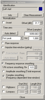
The total offset is shown as samples in the option part of each measurement. That would be time of flight plus latency, I think. Although in the snap below the offset seems rather high.To my knowledge HOLM does not ever do a "time of flight" calculation, or at least it is never shown if it is.
That's true, at least in the measurement signal there isn't a highest amplitude.In a frequency sweep signal there is no "highest amplitude" as the signal amplitude is flat.
So I wonder what he meant, and how the generated and measured signals are compared?
Attachments
The Holm app is very good, I've found no faults at all!
But, I've found that when using either my Pioneer VSX-922 or VSX-1122 HT amplifier together with Holm, I sometimes have to restart the amp due to totally corrupted phase curves.
After restart everything works okay again.
But, I've found that when using either my Pioneer VSX-922 or VSX-1122 HT amplifier together with Holm, I sometimes have to restart the amp due to totally corrupted phase curves.
After restart everything works okay again.
The total offset is shown as samples in the option part of each measurement. That would be time of flight plus latency, I think. Although in the snap below the offset seems rather high.
That's true, at least in the measurement signal there isn't a highest amplitude.
So I wonder what he meant, and how the generated and measured signals are compared?
1st - I am aware of the offset in samples, but I am not sure that this was ever intended to be the delay time in samples, just the start of the impulse from some arbitrary point in the output signal waveform. If this is truly the delay in samples, nowhere in the program does it state this. At any rate, who cares what the total delay time is, that's completely arbitrary as well. what one needs to know is the relative phase of the different measurements and this is perfectly accurate in HOLM (contrary to what is being claimed.)
2nd - when I reread what was stated I have trouble believing that Ask ever said this since it doesn't make any sense for a sweep. I am not sure that it makes any sense for any signal, since the waveform going into the speaker is modified by the speaker in ways that will change the "peak amplitude" almost randomly. As was stated, one would have to do a cross-correlation to find the real peak energy delay.
Last edited:
1: Yeah, not sure what the total offset means. I'll look into it. Doesn't really matter, as you say. It's the relative offset that's important.
2: True. I was thinking about how HOLM might align the signals for analysis. It can do the same with two imported files. With swept sine there isn't any highest amplitude in the test signal, so I was wrong about that. DiffMaker Software does some kind of analysis (which you can see in the log) to align files.
2: True. I was thinking about how HOLM might align the signals for analysis. It can do the same with two imported files. With swept sine there isn't any highest amplitude in the test signal, so I was wrong about that. DiffMaker Software does some kind of analysis (which you can see in the log) to align files.
The answer was "The highest amplitude of the test signal is time aligned with the highest amplitude of the response signal with that difference in time being the distance to the transducer." That seem pretty darn clear. Loudness equals distance.
I would not interpret it that way at all. One thing to remember too is that Ask's native language is not English.
As we know Holm converts the measured result to an impulse response. My interpretation of the above is that highest amplitude above refers to the highest peak in the impulse response. Compare the highest peak in the test signals impulse response to the highest peak in the recorded impulse response and you have (not taking into account latency) your time of flight. Provided the latency on the sound card is constant, once you lock time zero, all measures of time of flight are relative which is why provided latency is constant it gives you good relative phase of the drivers, which is perfectly usable for crossover design.
Tony.
- Home
- Design & Build
- Software Tools
- HOLMImpulse: Measuring Frequency & Impulse Response