Well, that's enough for a start. But remember to add the resistor in the future (that will alleviate the transistor power dissipation).
The diode current is not needed to be so high. 3-10mA is enough.
So use a 400mW zener, and resistor between GND and zener can be around 4.7Kohm.
The thick is.... provided that you have changed the 1k resistor to 4k7, add a 220uF to 1000uF electrolytic capacitor in parallel with the diode (+ terminal to base, - to -Vss, of course ;-).
That will create a RC delay of the base voltage, that will take around 1 to 2 seconds to raise from 0 to 13V. This will delay IR2010 turn on.
Simple, isn't it? Do you like it? 😉
Try it and tell me how it goes.
OK! I have try to changed the 1k resistor to 4k7 and add a 470u inparalle with the zener diode.
The final result is good. The power Rail is success working!
so , i remove the 4.4ohms power resistor from terminal.
And connect a 4ohm speaker to the terminal.
At turn on , it got a big bomb-sound.
And trun off, it also has big bomb-sound.
did you also get ??
how could we solve this problem?? add a relay??
Another problem , after turn on power to normal state.
I hear some high-frequency sound from speader.
And it sounds like Vary-frequency, the high-frequency change always.
does is because of i haven't connect the feedback network??
the feedback network RC low-pass filter , use 1k/1w and 220p.
is it good??
Well, at least we now know what the problem was! This is a big improvement.
Now you have to measure two signals carefully on power-up. Use two probes, one for the output of the comparator (one of them), another for the switching node and display both of them simultaneously on your oscilloscope.
Then power it up. At some point, you should see a clear, good, and 50% duty cycle signal at the comparator output and _AFTER THAT_, the switching signal at the output should appear suddenly, both of thems remaining that way and still looking good.
If both signals appear at the same time, or the second one appears before the other is 50% and stable, you must put a bigger capacitance in place of the 470uF you have just added to delay driver turn-on a bit more.
Tell me also what bootstrap cap value are you using now. And please, post a photo of your prototype just to have a general idea of how it is built so I can help you further.
Do this test with a R load (not speaker).
I test the two point , yes you are right!!
when The output in switching node has square wave.
the comparator output still not into stable.
so, i replace the 470uF become 1000uF.
but it not help too much , i replace it by 2000uF , and test again.
But still didn't enought. because of i always saw the switching node's wave appear.
The comparator output's hi-side of square wave still rising up.
i think maybe is my smps's soft-start too slow.
I'll try to make my smps's soft-start time become shorter.
thank you for your helping today.
I'll tell you the result tomorrow....thanks
I want know one , the turn on bomb-sound is cause by it???
The modulator shouldn't take so long in starting. Something else is wrong.
Can you monitor the + and - rails for the triangle generator and for the comparator, and test if they grow so slowly to their final value?
If you have the possibility, try to feed the opamps and comparator from another supply, and the power stage and driver from your SMPS. You can even add a switch or something like that to the driver's supply so that you can turn it on when the modulator is ready.
The bootstrap cap is also important: too high valued and you will get a nasty "tick" at power up. It should be 1uF or so.
And yes, the improper sequencing is producing your noises at power up and power down. Output stage MUST always turn on and off when the modulator is estable.
OK. tomorrow i will try to use another power supply for opamps and comparator.
my bootstrap cap is a 1u//104 .
maybe i will take out smps's soft-start function , let the smps's rail voltage can reached fast.
Maybe it will improment the situation.
tomorrow i will also show the picture to you...
my bootstrap cap is a 1u//104 .
maybe i will take out smps's soft-start function , let the smps's rail voltage can reached fast.
Maybe it will improment the situation.
tomorrow i will also show the picture to you...
I has another question about the core of the LC filter.
When the amp is on working , the L get heating.
Is that something wrong ??
Pierre , could you tell me what kind of core you are using??
could you tell me the color of the core ??
When the amp is on working , the L get heating.
Is that something wrong ??
Pierre , could you tell me what kind of core you are using??
could you tell me the color of the core ??
The coil shouldn't heat up with no signal when the amp is powered. Your core is still not suitable.
I used T106-2 from Micrometals.
Best regards,
Pierre
I used T106-2 from Micrometals.
Best regards,
Pierre
dose the t106-2 micrometal core is a Iron power Core ??
If my core in now , not suitable .
will it effect my whole test??
Like noise , big idle current , turn on/off "tick" sound??
If my core in now , not suitable .
will it effect my whole test??
Like noise , big idle current , turn on/off "tick" sound??
Have a look at:
www.micrometals.com
Your core will suffer from high losses, ruining the efficiency of the amplifier, and may even saturate, possibly destroying your mosfets when heavy loading is applied.
If I were you, I would select a better one before continuing.
www.micrometals.com
Your core will suffer from high losses, ruining the efficiency of the amplifier, and may even saturate, possibly destroying your mosfets when heavy loading is applied.
If I were you, I would select a better one before continuing.
because the inductor not OK yet..
so , i try to solve the turn on and turn off "tick" sound
All testing with 4.4ohms resistor be a LOAD.
AND remove the feedback resistor (R33).
1.
i got a question about turn on tick sound.
now , we try to make control circuit power on delay.
Let the mosfet's power stable first.
But when the gate driver IC turn , the output before LC filter.
Its square waveform appear sunddly.
I think it must will get pulse to make turn on tick sound.
And when turn off , the polarity of the Inductor reverse.
It will get a DC offsect too, It will get a turn off tick sound.
am i wrong ??
If i am right ... it seems can't solve by power on delay.
Or that's because of my output have DC offset to get turn off tick sound??
2.
All testing before now , i just connect LT1016 pin3(-) to gnd with a 1k resistor in serise.
Now I connect the U12(TL082) to the PCB , and remove c23 and r27 , just connect a 47k resistor cross U12's pin2(-) and pin1(out).
But the test result doesn't good , the output dcoffsec become more.
It get 1v DC offset. The waveform looks only positive side get more amplitude.
3.
I try to connect the feedback circuit , I know it is not good.
I add a RC low-pass , 1k/1w with a 200p , and serial a R33=33k connect to U12a pin2(-).
But it got something strange.
My 7815's output shun down , when i connect the R33.
And get big current ,too.
The 7815 became normal while i remove the R33.
I don't know what's happen??
4.
About the feedback circuit .
I try to understand why the feedback circuit can help system stable.
But i still didn't get answer yet.
Why we sum of the signal and output signal will help system stable??
I test the waveform in feedback RC low-pass filter output.
It still a square waveform. Just smooth the square.
It get +/-50v square wave , but no ringing.
what is the purpose about feedback RC low-pass??
does't the rc low-pass filter reduce the output square wave ???
Just one suggestion:
Try to get a transformer and linear power supply and throw your SMPS away, at least until you have debugged the amplifier.
And get a better inductor.
You must start from very well known conditions, and your SMPS is now more a variable than a fixed condition. Without this, you will only go in circles but won't reach a solution.
I have connect the power supply of comparator and opamp to a separate power supply, and remain the driver and mosfet to SMPS.
Before you have said , improper sequencing will produce noises at power up and power down.
what is the proper sequencing ??
Turn the comparator and opamp on first ,And then turn the driver and mosfet on ??
so , turn off sequency , we have to turn off the drvier and mosfet off first or not ??
Before you have said , improper sequencing will produce noises at power up and power down.
what is the proper sequencing ??
Turn the comparator and opamp on first ,And then turn the driver and mosfet on ??
so , turn off sequency , we have to turn off the drvier and mosfet off first or not ??
Comparator and opamp connect to separate power supply +/-15v.
The Gate Driver IR2011 and Mosfet connect to SMPS +/-45v.
1.The speaker noise is disappear.
2.I turn on the power supply first to get +/-15v First.
And make sure the comparator output waveform done.
It looks very good. Only a little ringing.
3.Turn on the smps power , It still get turn on tick sound.
But the turn on tick sound get little.
Turn off tick sound still remain.
4.I ask my manufactory of Inductor , he tell me the material of Core is T131-52 by micrometals.
Dose it not suitable for Filter ?? I don't know what material of T131-52 is.
Manufactory tell me the material of t106-2 get very low AL value.
If I use the core , It will need more than 30 turns to get 20uH.
Maybe tomorrow will get the new t106-2 core.
I will try testing again.
Yes, proper sequencing is:
-Turn on: first modulator (opamp+comparator), then driver+mosfets.
-Turn off: first modulator, then drivers + mosfets.
About the coil, that isn't suitable. You really need a low Al value, and what if you have to turn 30 turns (you really need 39, in fact)? If you are trying to build a Class-D you have to be prepared to suffer!
Who is your inductor manufacturer, btw?
Best regards,
Pierre
1. Turn on , we have add a capacitor(1000u) to delay gate driver power on. But Turn off , Then seem to be turn off on the same time.
Yesterday , I use three linear power supply , one for smps , two for +/- 20v to 78xx to get +/-15v and +/-5v.
I try to let the smps power still on , and turn of the others power supply that supply +/-20v.
I saw the smps's power supply's current display rise up.
Maybe I got something seauency wrong . I will try again.!
2. About the Turn on/off sequency:
How do you did turn off driver+opamp first ??
If you turn on driver+opamp First, It should be turned off last, right??
3. I'sorry , I let you get confuse. It's not a Core manufactory ,
It only a Factory for ODM the Inductor and transformer.
So , the inductor have to use Low-AL value Core.
I will tell the factory to find the suitable core.
Thanks a lot.!!!
Because my new core do not get yet...
so , could you teach me some about the FeedBack ??
I just saw a app note about opamp feedback.
The feedback seems to be reduce the siganl we don't need !
You told me that add a RC filter between feednet network.
does the RC filter have to cut out the 200k square wave ???
If yes , I use a 1k and 104 to do the filter , Is that righ?
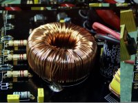
I have got my new Core , I use the micromatels T180-2 core.
It shown by photo.
I will show some picturn
1. the core , OD=50mm , 22uH
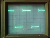
2. the output square waveform , 20v/div , 2us/div
It looks good.
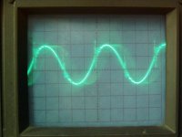
3. the output wave after LC filter , C=440n , 2v/div
It looks have DC offset about 1v.
I don't know why it has so high DC offset.
If square waveform is good, almost 50% duty cycle
Why does it get high DC offset ??
4. The U12A opamp, i want to use a 47k parallel a 200p capacitor.
It that OK ??
5. About Feedback circuit , 1k/1w and 0.1u cap , to do a RC low-pass filter.
And serial a 33k connect back to U12a's pin2(-) .
Does 33k to high ?
It shown by photo.
I will show some picturn
1. the core , OD=50mm , 22uH
2. the output square waveform , 20v/div , 2us/div
It looks good.
3. the output wave after LC filter , C=440n , 2v/div
It looks have DC offset about 1v.
I don't know why it has so high DC offset.
If square waveform is good, almost 50% duty cycle
Why does it get high DC offset ??
4. The U12A opamp, i want to use a 47k parallel a 200p capacitor.
It that OK ??
5. About Feedback circuit , 1k/1w and 0.1u cap , to do a RC low-pass filter.
And serial a 33k connect back to U12a's pin2(-) .
Does 33k to high ?
Attachments
- Status
- Not open for further replies.
- Home
- Amplifiers
- Class D
- hlpe ! Turn on get big current