1.I'm so sorry , i still not understand about "draw around 60-70mA from one rail , 60-70 from the other"
Forgive about my bad english.
2. OK . I'll buy another coil that saturate high freq. response.
3. so , you mean bad coil will get current consumption??
That why when i reconnect the coil to the PCB , I always got
bigger current ??
4. If the coil is good , what is waveform at output of coil ??
Forgive about my bad english.
2. OK . I'll buy another coil that saturate high freq. response.
3. so , you mean bad coil will get current consumption??
That why when i reconnect the coil to the PCB , I always got
bigger current ??
4. If the coil is good , what is waveform at output of coil ??
I saw the "Turn on/off transients " and studing .
your circuit has deadtime control.
do you think i also have to add the deadtime control ??
I think the IR2011 has build in deadtime control. do i get wrong ??
If Ir2011 doesn't has deadtime control , what effect will have ??
your circuit has deadtime control.
do you think i also have to add the deadtime control ??
I think the IR2011 has build in deadtime control. do i get wrong ??
If Ir2011 doesn't has deadtime control , what effect will have ??
Dead time control won't hurt. You have some kind of it with the diodes in antiparallel with the gates resistors. But I recommend that you add some more dead time at the inputs.
That can be easily done by adding a RC filter at each driver's input, with a diode in antiparallel with the R (similar to the gates but with a cap in parallel with the input).
Start with a 1n4148 diode, 3.3 resistor and 47pF cap.
You can always remove it if you find it is not needed...
But I am afraid that your main problem is the inductor and that you perform your testing without load.
About the correct output waveform, you should get some kind of sine (somewhat distorted in some cases), at the switching frequency, with possibly some spikes or ringing of much higher frequency. The amplitude of the output sine depends on the filter, sw. frequency, voltage of the rails and load. You must reduce it to around 2-3Vpp typical.
20uH + 440nF capacitor and 200KHz should yield something like that at +/-40V rails.
could you teach me how to caculate the Output LC filter??
If my rail = 45v , and Tri-wave freq=200k , how to decide the L and C??
If my L > 20u , it'll better or worth??
Later I'll test with load.
If my rail = 45v , and Tri-wave freq=200k , how to decide the L and C??
If my L > 20u , it'll better or worth??
Later I'll test with load.
The easiest way is to design the filter if you don't have much experience or mathematical background is to use a simulator like Spice, Protel, Electronics Workbench, etc.
To know the output ripple level, you can plot its frequency response and then know how many dB's of attenuation it provides at a given frequency. Then, Att=10^-(dB/20)
If, for example, a given L, C and Load combination produces a 30dB attenuation at 200KHz, att=10^-1.5=0.031
So if your rails are +/-40V=80V total, you will get aprox. 80*0.031=2.48Vpp of output ripple.
You must also avoid too much peaking at the filter resonance (that is easy to calculate, Fp=1/(2*pi*sqrt(L*C)), ("sqrt" being the square root). A given L C filter is optimal for a given R load, so there is always a compromise if load is not fixed. You should design for R=4 or 8 ohms, for example.
Filter resonance (Fp) should be located about 1.5-2 times the upper desired frequency. For 20KHz response, 35-40KHz is a good choose.
So , now we use L=20u and C=0.44u
By formula Fp=1/(2*pi*((L*C)^(0.5))) =53.651kHz , am i right??
I have used the Pspice to sumulation, now i have got some concept.
I just getting a new Coil = 20u , and manufactor tell me that
the matiral of the core is low-u core , should be suitable for
me to use for filter , i will try it again , later i will tell you
what it happen .
I just read "Class D Audio Amplifiers - Theory and Design" from ESP webside.
He talked about the feedback network , he mean using a RC low-pass filter connect from swiching node.
I saw the circuit from yours in "Turn on/off transients "
your feedback network is paralle a R and C.
It seems not a RC low-pass filter , so , how should i have to do ?
He talked about the feedback network , he mean using a RC low-pass filter connect from swiching node.
I saw the circuit from yours in "Turn on/off transients "
your feedback network is paralle a R and C.
It seems not a RC low-pass filter , so , how should i have to do ?
I have tried new component , It looks good.
I'll paste several pictures.
when i reconnect the Coil and turn on the power(no load).
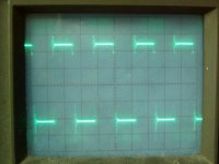
The waveform of switch node is good form +45v to -45v square wave.
And the waveform of output is 4Vpp, but it got some ripple.
I just connect the 4.4ohms resistor to the terminal.
when i turn power on , the power supply current rise up to 8A.
But the Output MOSFET didn't get heating.
I touch my SMTP's mosfet ,it get heating. i don't know what happen.
so , i remove the resistor, and trun on power.
It go to stable , and i connect the resistor again while power on.
Power's current didn't get rising, and output waveform still 4Vpp sine wave.
do you have any experience about it??
does it that i didn't connect the feedback network yet?
do i have to use a Relay to make a delay ?
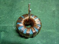
the picture is my new Core:
I'll paste several pictures.
when i reconnect the Coil and turn on the power(no load).
The waveform of switch node is good form +45v to -45v square wave.
And the waveform of output is 4Vpp, but it got some ripple.
I just connect the 4.4ohms resistor to the terminal.
when i turn power on , the power supply current rise up to 8A.
But the Output MOSFET didn't get heating.
I touch my SMTP's mosfet ,it get heating. i don't know what happen.
so , i remove the resistor, and trun on power.
It go to stable , and i connect the resistor again while power on.
Power's current didn't get rising, and output waveform still 4Vpp sine wave.
do you have any experience about it??
does it that i didn't connect the feedback network yet?
do i have to use a Relay to make a delay ?
the picture is my new Core:
Attachments

The waveforms look almost good.
First, the big current problem:
1. What is the inductance of that coil? Have you measured it?
2. Have you measured the switching node and output waveform when there IS a load connected? Maybe it is going to one of the rails (the negative one, it can't be another), all the supply current is going to your load but as the low side mosfet of the amplifier is fully on it is dissipating little power (Rdson^2 * Iload ). So, you HAVE to measure the load voltage and tell us.
3. The testing you have shown is with or without feedback? The (2) problem should only happen _with_ feedback
And now the other details:
Don't worry too much about the high frequency ringing in the output waveform, it can be reduced by the addition of dead-time and slowing down the turn-on/off of the mosfets (increasing gate resistor to, say, 18 ohm).
About feedback: please try to fix the circuit without feedback first, then, when everything is ok, take feedback from the switching node, pass it through a RC lowpass filter. (my R||C configuration was a compensation zero for feedback _after_ filter, you don't need it at first instance).
Keep on working, we are very near the solution...
1. the inductance of coil is 20uH.
2. yes , if there is a LOAD, the switching node is going to negative rail when turn on power.
I try hold on the power after turn on.
After few secends about 3 secends, the system become stable.
The output waveform is going to narmal.
3.The test i have showed were without feedback.
I directly connect the Lt1016 audio input seria a resistor 1k to gnd.
And i have changed the gate resistor to 100ohm.
4.I try to test the +/-rail when turn power on .
Ex. +rail , it start rise up to 20v and then stoping.
in now , the current is 8A. after few secends.
Current down to normal , the +rail is able going to normal voltage +45v.
5.Just like i said , if start i didn't connect the load.
The power on is normal , didn't have any problem.
Mmmm. Very curious.
Let me summarize all, just to see if I have understood it all:
- When no load, at turn on everything works ok, output shows the ripple your shown in the photo. What is the current consumption from each rail?
- When load is connected, output goes to negative rail (please note that's why you get 8A consumption: all of them go to the load), and after 3 seconds or so you get the normal ripple centered at about 0V, is that right?
- All the tests above are without feedback and 0V at the input of the opamp.
Well, you will need to check some waveforms at the start, in the 3 first seconds where everything works wrong. You can start with the supply rails (perhaps the SMPS is not starting OK under heavy load), the triangle (is it there during that time?), the outputs of the comparator (are they 50% or start at another very different duty-cycle?) and then the gate waveforms. I suggest that you start in this order and post your results here.
Best regards,
Pierre
1. i don't really know how many current consumption.
because the power system i made is a smps. DC/DC convertor.
The smtp system have current consumption by ifself.
i just can guess , it seems has 200mA per Rail.
2.The current consumption that i see it from power supply's amp display.
It include smps's power consumption. About 350mA.
when amp go to normal,the output DC offset is 0.3V i meansured.
3. Yes! the time that get big current,the smps not go to stable.
It only get starting. The +/-Rail not go to stable voltage.
Just i said last time, the Rail stable voltage is 45V.
It only get 20v and stop , while get big current.
when system go to normal , the +/-rail gose to correct voltage fast.
4. I'll test the others waveform , and tell you.
5. My smps has Soft-start function , will it effect amp starting??
I'll tell you what I think it's happening:
The SMPS takes a while to achieve proper output voltage. Your driver stage is working before your modulator is estable. When you have no load, you will have a negative output transient until the modulator starts and the square wave is correctly generated.
When you have load, that negative output at start up produces a huge current consumption at the load, so your SMPS may be protecting itself or working wrong, and hence takes much more time to estabilize (3 seconds).
If the power supply soft-starts, your modulator supplies may not be estable until it starts completely (have in mind the drop of the regulators and series resistors), then you have erratic behaviour.
That's why I suggested to delay driver turn on (or inputs tied to 0 logic level so both mosfets are off) until all is estable.
You always need to ensure that the modulator is estable BEFORE the output stage and driver are activated. With a IR2110 that's easy because it has a SD pin that can be controlled with RC delay.
The test to verify all this is easy: feed your modulator with a separate lab. supply, after that, apply power to the output stage and driver with your SMPS if you want.
However, at this point, I really would try to try first with a another power supply that doesn't have the sometimes weird effects of SMPS. If not, you may never know where the problems come from.
Don't you have access to a toroid transformer? A 300VA, 25+25VA is enough, you can go up to 35+35VA if you want, then a bridge rectifier and a couple of 10000uF/50V caps.
I strongly suggest that you build a test conventional PSU.
Do you really follow me? It is important that you understand it well in order to solve the problem.
Yes! i also feel it is because of the power not go to stable.
The driver IC has been worked.
In my circuit , could i add some thing to delay driver turn on >??
now , i test environment , my input alwaly tied to gnd serial a 1k.
The driver IC has been worked.
In my circuit , could i add some thing to delay driver turn on >??
now , i test environment , my input alwaly tied to gnd serial a 1k.
Yes, you can do something, now that I think of it: you can delay the supply to the driver. I mean, the 12V referred to -Vss.
I don't know how do you get that voltage, but I suppose you use a 7812 regulator or similar.
Please detail how do you get that voltage and I wil tell you how to delay it the easiest way.
I don't know how do you get that voltage, but I suppose you use a 7812 regulator or similar.
Please detail how do you get that voltage and I wil tell you how to delay it the easiest way.
My transfomer has two pair output , one for amp is +/-45v
and one for pre-amp , compartor +/-20v to down
to +/- 15v and +/-5v using 78xx and 79xx.
The power of IR2011 , 15v depend on -45v.
I use a zener , R and BJT to get.
do you mean if we let the main power getting stable first , and then trun on the IR2011 driver , I just can slove this problem.??
and one for pre-amp , compartor +/-20v to down
to +/- 15v and +/-5v using 78xx and 79xx.
The power of IR2011 , 15v depend on -45v.
I use a zener , R and BJT to get.
do you mean if we let the main power getting stable first , and then trun on the IR2011 driver , I just can slove this problem.??
I mean that maybe holding the DRIVER power down for a while, so UVLO of the chip acts (below about 8V it shuts down), you can give time for the modulator, etc circuitry to estabilize and then the PWM signals are ok, so you don't get the negative transient when the driver turns on.
About your supply for the driver, that's perfect for this trick:
First I will tell you how to do it (check that now it is done this way), and then the modification you need to delay driver power:
GND connected to BJT (NPN) collector, with a power resistor in series. A value of around 100-300ohm/2W is ok. Emitter goes to driver 12V (referred to -Vss). Base has a 13V or so zener diode (cathode to base) to -Vss. Base also goes to GND with a resistor of around 3k3 to 7k5 ohms. Is this ok?
(The 100-300ohm resistor is good so you don't have the full ((45V-12V) x Idriver) dissipated in the BJT. It produces a voltage drop that shuld be around 20V and depends on the current drawn by the driver).
Is it done this way? Please detail your values and connectionso of this part of the circuit first, then I will calculate the needed modification for you.
Yes! my structure just like you said.
But i didn't have the resister between Gnd and collector.
I directly connect the BJT's Collector to Gnd. Because of I chose a BJT (HT112) that has 100v Vceo , Ic=4A.
The zener i use 15v/1W. The resistor between Ged and Base I use 1k/2W to get about 30mA. Maybe can use little.
I have a ideal, i add a relay to Ir2011's VccPin and 15v that dependen on -45v.
- Status
- Not open for further replies.
- Home
- Amplifiers
- Class D
- hlpe ! Turn on get big current