hi
i have recently obtained two dead amps hitachi
both had blown output transistors, which i replaced
they sound ok, but i would like to improve them to smoother more warmer sound
i was thinking upgrading the capacitors in signal path
maybe bypasing tonal correction completely, even sometimes it comes handy
getting rid of low-filter and so on
there is audible noise on the amps output with highly efficient speakers, which i would like to reduce
any sugestions for transistor swapping?
i do not want to make too much of a rebuilding, they are pretty decent as they are
any suggestions are wellcome
thanks
Attachments
no suggestions?
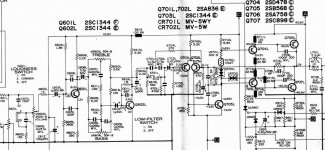
well, so far i removed low filter, those two mylar 0.15 uF capacitors, R618, R701 and its paralel cap with no name, R704
and conected R616 directly to C703
than i used spare mylars to bypas those two electrolytes in/out Q602
that improved sound a little but there is still an noise to address
i replaced first transistor Q601 with selected low noise one and it helped significantly
i can tell for sure because i must go with volume higher to detect the hiss in headphones and i have two of these amps and i am working on just one of them, so the comparison is easy and almost objective
i think i should go ahead and replace all first five transistors with low noise ones and see how much the hiss goes down
all i need to achieve is no noticable hiss when using headphones
its already fine with speakers
i wonder if any one experienced could tell me what is the critical part to play with which has most effect on noise level
any other suggestion to improve the amp?
Hi, I recently picked up this amp at a thriftstore. It works and sounds pretty good. One possible mod I want to try is replacing the indicator bulb with an LED. The only problem with this, is that I have no idea what wattage the original light bulb was. I already burned out a blue LED playing around with this. Do you know what kind of resistor is necessary to get an LED in there? Thanks.
hi dmunky
well, replacing the lamp with the led is simple, you just have to understand that the lamp is powered with quite high voltage, so you need to put resistor in series with the led
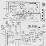
if you look at the schematics, the lamp is powered from one of two secondaries of trafo, those two secondaties aro providing +/- 40 volts after filtration, i would guess those two trafo seconadries are 36volts ac
tha lamp is powered from those 36 vols thru 100 ohm resistor and a diode
i do not know what voltage is actualy on the lamp, I would have to measure it, since there is nothing in manual
since it is not fully filtered, there is no capacitor on the lamp, its hard to say
so to come up with resistor for the led is not easy
you should power the led from well filtered and stabilized voltage, +/- 14 volts available in the amp to power the preamp section
just take +14 and ground and calculate the resistor, that just ohms law
ed
well, replacing the lamp with the led is simple, you just have to understand that the lamp is powered with quite high voltage, so you need to put resistor in series with the led
if you look at the schematics, the lamp is powered from one of two secondaries of trafo, those two secondaties aro providing +/- 40 volts after filtration, i would guess those two trafo seconadries are 36volts ac
tha lamp is powered from those 36 vols thru 100 ohm resistor and a diode
i do not know what voltage is actualy on the lamp, I would have to measure it, since there is nothing in manual
since it is not fully filtered, there is no capacitor on the lamp, its hard to say
so to come up with resistor for the led is not easy
you should power the led from well filtered and stabilized voltage, +/- 14 volts available in the amp to power the preamp section
just take +14 and ground and calculate the resistor, that just ohms law
ed
Hi Adason and other readers,
a friend of mine gave me an old HITACHI HA-330 that works bad.
After few minutes of great job, a big "boum" in speakers happens as if the power supply failed. I shut it down some minutes and then I can have it (after power it up ;-) working good for less minutes than first try.
I think (but I'm not a specialist) that the power supply is sick.
I came on this thread because I search Internet to find the schematic of the Hitachi but I found an extract in 'resize.jpg'. Where is it possible to find it entirely ?
More, is anybody has an opinion about my problem ?
Thank you in advance
(and sorry for my poor english)
Nioux
Hi nioux,
I have complete schematics and service manual, I can scan it and send it to you. I sent you an email a while back, but you did not reply.
ed
I have complete schematics and service manual, I can scan it and send it to you. I sent you an email a while back, but you did not reply.
ed
Hi Adason !
First change C705 from 100uF to 220 or higher, after that you will get lower freq. I , don't see all schematic, put on forum & after that we will talk.
Regards zeoN_Rider
First change C705 from 100uF to 220 or higher, after that you will get lower freq. I , don't see all schematic, put on forum & after that we will talk.
Regards zeoN_Rider
Hi zeonrider,
I no longer have the amp, I was just offering the help to nioux request.
thanks anyway
as far as I remember, the amp at the end worked perfectly and sounded good for such an old design, I was not too happy with noise, than I bypassed corretion section and all was fine, I left loudness on and off
I gave it to a friend, he is still using it
this is old thread, if nioux or anybody else wants, I can post or email schematics
ed
i tried, but the images are too big for diyAudio site
if i reduce them to 100k, they are unreadable
i can email them who is interested
if i reduce them to 100k, they are unreadable
i can email them who is interested
adason said:this is just an example how much I had to srink it to pass the criteria for this site!
i do not understand how some people can post multiple pictures of enormous size
Hi Adason,
Those pictures are hosted on other places.
Hi adason!
Hope you'r still there. Can you send me the Lo-D (Hitachi) HA-330 schematics? It's so difficult find this scheme in my location. Sorry for bad English.
Hope you'r still there. Can you send me the Lo-D (Hitachi) HA-330 schematics? It's so difficult find this scheme in my location. Sorry for bad English.
adason said:i tried, but the images are too big for diyAudio site
if i reduce them to 100k, they are unreadable
i can email them who is interested
The key is knowing which format to use. Convert your images to 4 levels of gray GIF. 100k of this will alow you to post a rather huge image.
ok ilimzn
i did that, i converted jpeg scans to gif gray color, but they were still 360kb, so I had to shrunk them furter to 1000x1000 pixels, another limitation, attached is the result, its readable, but much uglier than original, whoever wants original, just email me, as i said before
i did that, i converted jpeg scans to gif gray color, but they were still 360kb, so I had to shrunk them furter to 1000x1000 pixels, another limitation, attached is the result, its readable, but much uglier than original, whoever wants original, just email me, as i said before
Attachments
I'm a sucker for anything old. Picked one of these up from the trash, looks fine except the transformer tests bad. Does anyone have the full hi-res schematics they can send me along with a part number or winding spec on the transformer?
Thanks!!
Thanks!!
To BoredTinkerer:
Second (coil?): Middle point of trans. wiring - point5(pcb)-near grey colored resistor, nears of wiring (to next plus-minus) -points number 4 and 3 - near transformer place.
30x30 volts - second winding, but i mean it's 25-22 volts per shoulder was enough.
Sorry for bad english.
Dmitry.
Second (coil?): Middle point of trans. wiring - point5(pcb)-near grey colored resistor, nears of wiring (to next plus-minus) -points number 4 and 3 - near transformer place.
30x30 volts - second winding, but i mean it's 25-22 volts per shoulder was enough.
Sorry for bad english.
Dmitry.
- Status
- Not open for further replies.
- Home
- Amplifiers
- Solid State
- hitachi ha-330 modification