Yes Lineup,
I don't know why this was not proposed by Jean Hiraga himself. 🙂
maybe it is not a Jean Hiraga then?
hi!
My LT spice simulation does not show any improvement with this 100r resistor - even upside down - THD slightly worse with this resistor.
My LT spice simulation does not show any improvement with this 100r resistor - even upside down - THD slightly worse with this resistor.
Osscar,
My LT spice shows cross conduction above 10khz near clipping without resistor
but with resistor 560ohm, it gives better results.
My LT spice shows cross conduction above 10khz near clipping without resistor
but with resistor 560ohm, it gives better results.
It is not an 8-watt Le Monstre but a bipolar Le Classe A design of Hiraga, beefed up to 30 watts. It should be nice sounding. It has excellent behaviour to an electrostat for instance - on 0,5 uF still no ringing or overshoot.HI
what about this kit?
jim's audio
how knows some thing about it?
Now try that with Le Monstre (it does ring a bit and can't drive low impedance at 20 kHz very good).
The parts list looks ok, give it a try.The power supply will cost you 5 times the cost of the amplifier boards 🙄
thanks for the information about the ''super le monstre''
in fact i have an ACOUSTAT 3 and i am very curios to listen it
i do have a good pwr supply, i am considering to use a regulated voltage that is capable to drive 17 amps
best regards,
williams
in fact i have an ACOUSTAT 3 and i am very curios to listen it
i do have a good pwr supply, i am considering to use a regulated voltage that is capable to drive 17 amps
best regards,
williams
thanks for the information about the ''super le monstre''
in fact i have an ACOUSTAT 3 and i am very curios to listen it
i do have a good pwr supply, i am considering to use a regulated voltage that is capable to drive 17 amps
best regards,
williams
It will work for sure but do not call it 'Hiraga' because it will behave and sound
different due to the parts delivered by JMS (I bought bare PCB's only, they are good BTW) since I have got all the original Xtors. and also because the PSU is crucial for the Hiraga amplifiers. But yes, 0.5F /35V capaciators per rail is expensive! No toroidal Xformer. Even an EI core with screen is much better. A true Hiraga is an expensive project!.... My thoughts.
hi all,
yes it is expensive thing to be an audiophile, specially with class a pwr amps
but i do have the power supply from an older project so after assembly the monster i will send a report,
best regards,
williams
yes it is expensive thing to be an audiophile, specially with class a pwr amps
but i do have the power supply from an older project so after assembly the monster i will send a report,
best regards,
williams
Last edited:
hi all,
yes it is expensive thing to be an audiophile, specially with class a pwr amps
but i do have the power supply from an older project so after assembly the monster i will send a report,
best regards,
williams
Yes please. Also I should mention that due the low damping factor of Hiraga's amps it may not work as well as some other topologies with MOSFETS ore more powerfull class AB, with electrostatic speakers. These amps reach the top of the best with big boxes (360 liters) like the 'pseudo' bass reflex Onken equiped with Altec 416, 415 or even 414 in smaller cabinets. Again, my thoughts!
=========================================
- Transistors in my May 2008 final version ( was doing this one day 1 month ago, 2008-05-31 )
input:
2SK170GR + 2SJ74GR .. IDSS is ~ 4-5 mA
... no problem using them without cascode, as 2SJ74 takes 25 Volt.
- But I added cascode at 6Volt level (half supply) with:
BC560C + BC550C
I do not remember, but probably this gives a bit lower distortion.
I usally avoid cascoding JFETs, unless I see there is some benefit from it.
- Second stage, drivers.
BD139 + BD140
Nothing mysterical. They are the best bang for buck drivers ever made and used in audio.
In this amplifier, Le Monstre, they will fit in very well regarding quality.
- Output transistors.
TIP41 + TIP42
I started out testing with MJ15024 + MJ15025 = TO-3 high power.
But these TIP41/TIP42 OnSemi devices performs better.
Probably because they have higher gain.
Rated 65 Watt and as they will only dissipate like 0.8 x12-15 VDC = 10-12 Watt for Class A,
there is no problem using these easy to find & budget price devices.
Lineup
And now I'm wondering what are you using in the 2013 version?
And could you recommend which PSU to build for this amp, is it preferable to use the original?
/Cheers from the other side of Kattegat
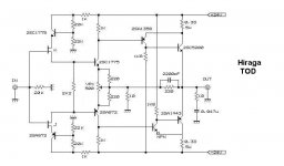
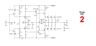
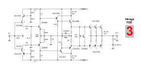
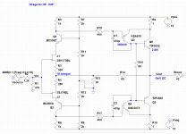
Hiraga TOD
My idea is using Jfet bootstrapped
as Diamond input buffer🙂
like first design
My idea is using Jfet bootstrapped
as Diamond input buffer🙂
like first design
Attachments
Last edited:

Fun circuit.My idea is using Jfet bootstrapped
as Diamond input buffer🙂
like first design
You dont need the transistors above the input that act as a stable voltage source - they will amplify the current on the 1 k and hence destabilise 😱 the source itself on the 22k/22k divider.
Hiya,
I decided to build an headphone amp based on the Monstre circuit.
My starting point was the one published by kk-pcb.
Since I wanted much less gain (and lower distortion) I had to touch the feedback resistors. Therefore I chose slow and low-gain driver transistors (the fairchild pair with only 4Mhz Ft) and also added a little compensation on them. I hope this wont make the amp oscillate.
The input jfets are not matched which I have in my scrap bin, likewise for the BC. One heatsink per channel will be used, good up to about 10W.
The two resistors R14 and R15 are just to reduce the power dissipation of the output transistors within the dissipation alu available.
My goal was to keep a nice harmonic spectrum (mostly 2nd and third) and plenty of power/current to drive eventually even orthos, and without using exotic transistors.
I wont start building it before a couple of months, since I have other stuff on schedule, but the simulation looks promising.
PSU will be the regulated sigma22 which I use on most of my headphone amps, with 80-120VA transformer.
Attachments
Good luck to your projects.
Which way you want to set the quiescent current?
Didn't you read some articles about this circuit?
Regards
Sam
Which way you want to set the quiescent current?
Didn't you read some articles about this circuit?
Regards
Sam
Which way you want to set the quiescent current?
What do you mean by "which way"? If you mean how much, it's about 200mA per output transistor.
Yes, I read the original articles online and all this thread. I cannot use 12x gain to drive phones, therefore I had to do what I did.Didn't you read some articles about this circuit?
If you think there are some mistakes in the schematic, please correct me 🙂
"Yes, I read the original articles online and all this thread. I cannot use 12x gain to drive phones, therefore I had to do what I did."
Why you have to use these large, slow output transistors? You only have to drive phones?
My opinion is, there are better solutions for a headphone amp in the DIY.
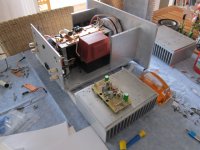
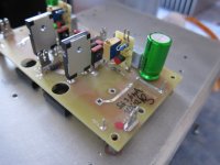
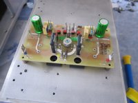
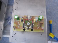
There is a pix of the last generation "Hiraga 8 Watt" from Klaus Scherm, Germany.
He changed drivers and output trans, and made a tricky setup with current sources for the input Jfets.
sounds great, and was successful at the poweramp shootout at the german "Frickelfest"
Endspiel/es02
Frickelfest 2012/hb/ff12_079
Frickelfest 2012/wl/1 (20 von 60)
Regards
Sam
Why you have to use these large, slow output transistors? You only have to drive phones?
My opinion is, there are better solutions for a headphone amp in the DIY.
There is a pix of the last generation "Hiraga 8 Watt" from Klaus Scherm, Germany.
He changed drivers and output trans, and made a tricky setup with current sources for the input Jfets.
sounds great, and was successful at the poweramp shootout at the german "Frickelfest"
Endspiel/es02
Frickelfest 2012/hb/ff12_079
Frickelfest 2012/wl/1 (20 von 60)
Regards
Sam
Attachments
Last edited:
- Home
- Amplifiers
- Solid State
- Hiraga "Le Monstre"