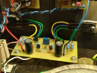
my La Monstre got new output transistors yesterday(2sc3284/2sa1303), I also reduced the collector resistors to 0.5R, I left the current the same around 1.3A, the supply voltage is +/- 19V.
sound? I was surprised, now it's even better than my JLH69, it got a kick in the lower frequencies, the middle and high are detailed, clear, the piano sounds like it's in my living room, just wonderful
sound? I was surprised, now it's even better than my JLH69, it got a kick in the lower frequencies, the middle and high are detailed, clear, the piano sounds like it's in my living room, just wonderful
Attachments
my La Monstre got new output transistors yesterday(2sc3284/2sa1303), I also reduced the collector resistors to 0.5R, I left the current the same around 1.3A, the supply voltage is +/- 19V.
sound? I was surprised, now it's even better than my JLH69, it got a kick in the lower frequencies, the middle and high are detailed, clear, the piano sounds like it's in my living room, just wonderful
looks good.
which pcb did you use? have a pic?
i have +/- 22V PSU. will this fit for your LeMonstre version?
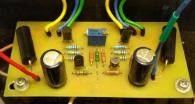
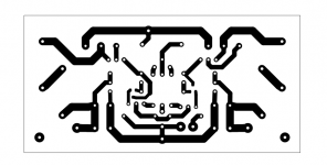
I made all the PCBs myself.
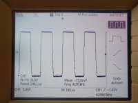
For voltage +/- 22V some resistor values should be corrected and it will work.
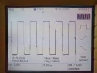
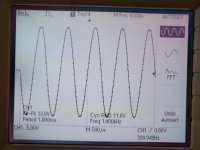
Here are a couple of pictures of the output signal on the scope at 8ohm load.
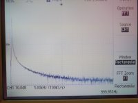
For voltage +/- 22V some resistor values should be corrected and it will work.
Here are a couple of pictures of the output signal on the scope at 8ohm load.
Attachments
I have seen a few people using the power supply kit from EBay Serbian Hifistor, what caps did people use in these boards? I’m having trouble finding 68000uf 25v caps that will fit these boards. I can find 16v will these be ok?
Matt
Matt
I made all the PCBs myself.
For voltage +/- 22V some resistor values should be corrected and it will work.
Here are a couple of pictures of the output signal on the scope at 8ohm load.
Nice PCB work!
Could you please provide a pcb template with the components placed?
Last edited:
Le monstre transistors
Hello Monster friends.
After a long time i finally decided to start my Le monstre project amp.
The target is to use a battery PSU.
I'm sure to use the 2sk170 and 2Sj74 available from DiYaudio Store matched already.
Regardin the output transistors i would like to use the 2sc2836/2sa1186.
What do you suggest me for all the rest.?
I found the original transistors but i do not know the brand. (2sc1775..2SA872...2SB716 and 2SD756) .
Better to go for the BC 560/BC 550 instead?
Do you have any other to suggest?
Is it mandatory to match those transistors as well?
Thanks in advance.
Maurizio
my La Monstre got new output transistors yesterday(2sc3284/2sa1303), I also reduced the collector resistors to 0.5R, I left the current the same around 1.3A, the supply voltage is +/- 19V.
sound? I was surprised, now it's even better than my JLH69, it got a kick in the lower frequencies, the middle and high are detailed, clear, the piano sounds like it's in my living room, just wonderful
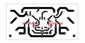
hi, i can not see 2sc3324 and its complementary on your board? and even not on on your pcb layout?
Last edited:
hi, i can not see 2sc3324 and its complementary on your board? and even not on on your pcb layout?
2SC3324 / 2SA1312 are SMD components and are located on the bottom of the PCB
https://hr.mouser.com/datasheet/2/408/2SC3324_datasheet_en_20140301-1150780.pdf
Attachments
Sorry about the basic questions but I’m about to order two transformers for these power supply boards. Do I need 9-0-9 secondaries or just 2 x 9. They are going to be sepetate mono blocks.
Thanks
Matt
Thanks
Matt
i think 9-0-9 and 2x9V is the same. you have two secondary windings, which you need for symmetric psu as for Hiraga.
You get 0 by connecting one of each 9V wires together when using a rectifier.
there should be many examples in the web
You get 0 by connecting one of each 9V wires together when using a rectifier.
there should be many examples in the web
I thought the 0 in 9-0-9 was a centre Tap. Why would they have two separate transformers for sale if they are the same thing?
you can use one transformer with 9-0-9 dual wireing
ore two transformers with 0-9 mono wireing
ore two transformers with 0-9 mono wireing
PCB layout
Hi All,
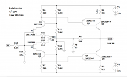
I am currently designing a PCB for a mosfet based LeMonstre amp with a topology similar to this:

I'm trying to decide what ground to attach the zeners, 22uF and 0.1uF capacitors used to supply the input BJTs. Traditionally any kind of decoupling capacitors should go to the dirty ground, but in this case any voltage variations on the ground have the potential to be injected into the input.
So.... I am wondering if these should be connected to the signal ground in this case, or perhaps even have their own ground which then connects to the clean and dirty ground at the star point on the PCB - this is what I am currently going with.
Any thoughts would be appreciated!
Greg
Hi All,
I am currently designing a PCB for a mosfet based LeMonstre amp with a topology similar to this:
I'm trying to decide what ground to attach the zeners, 22uF and 0.1uF capacitors used to supply the input BJTs. Traditionally any kind of decoupling capacitors should go to the dirty ground, but in this case any voltage variations on the ground have the potential to be injected into the input.
So.... I am wondering if these should be connected to the signal ground in this case, or perhaps even have their own ground which then connects to the clean and dirty ground at the star point on the PCB - this is what I am currently going with.
Any thoughts would be appreciated!
Greg
Hello Greg, your schematic is not Le Monstre but Hiraga Super Class A 30 Watt. What type of Mosfet do u use for your mods?
Hi,
I'm only using fets in the output stage, all the rest will be BJT.
Not sure which fet yet, probably IRFP240/9240 or similar.
Cheers,
Greg
I'm only using fets in the output stage, all the rest will be BJT.
Not sure which fet yet, probably IRFP240/9240 or similar.
Cheers,
Greg
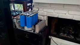
Just added 240kuf and it is no longer light in the bass. Caps from a Krell KMA200. I do have some space issues.....
Hahahaha you`re crazy 😀
Just added 240kuf and it is no longer light in the bass. Caps from a Krell KMA200. I do have some space issues.....
Hello,
I agree it looks crazy.
Using 75 volt dc caps for a 15/20 volt power supply.
The wiring to these big caps is rather long.
When you would have read the original Hiraga publications you would have known that especially with big caps it does matter where the wire is connected. In this situation the wires should be connected to the capacitor in the center.
Same with the big '' earth plane ''
And It seems with this way of connection the recharging and decharging of the caps is passing through te same wire.
Maybe add a nice high current choke ( LL2733/LL2771) A friend just did in his 20 watt Hiraga . Just adding caps will also put stress on transformer and rectifier. Better use a CRC or CLC like the French already did in the eighties.
Greetings, Eduard
- Home
- Amplifiers
- Solid State
- Hiraga "Le Monstre"