Hi Sergiu, thanks for the reply, as have already mentioned I was having resistors which adds up in series or parallel to get the desired values. As we have to use 1/2 watt resistor throughout, the desired values were not available here in 1/2 watt range. So calculated and found that from my inventory I had 1/4 watt dale mfr resistors and wanted to use them. So 3* 300 ohms is not actually 900ohms which I will put on board, rather Will be using 3 * 100ohms 1/4 watt resistor to get 300ohms at 0.75watts. Same for all other case too. I know it's a bit overkill but no other options for now. Afterwards if I get the desired values in a single Piece, I can ofcourse put wire jumpers. So wanted to keep it flexible...will make position for trim pot as suggested and share the same with you, will also increase the width of V+ and -( currently at 2mm), and also the entire tracks will be solder bathed and the overall layout will be thicker...Regards.
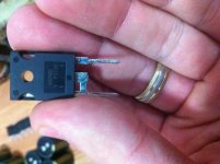
I'd double check your output transistor pinouts
Hi TVI, the transistors will be hardwired and will be mounted on chasis heatsink and will not be soldered on the board... so will take care of the pinouts when wiring the transistors, I have thought of putting relitimate connectors at the place so that it will be easy to plug in the wires and will be easy to remove the board if required for any future component replacement or modificatios ...regards
Last edited:
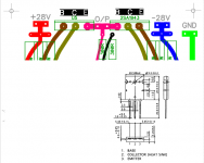
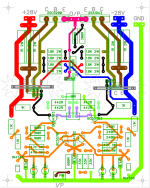
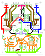
Hi, Sergiu. Pls find the layout with necessary modification. Have increased the width of tracks as suitable. I was about to place an order for a toroidal transformer (custom built.)
0--20 150va 0--20 150va,
0--20 150va 0--20 150va . All 4 in the secondary of a single transformer, will be using two different power supply units. Should I go for two separate transformers or this will be fine. Separate transformers will increase cost as well as take space.
So require your view...regards.
Attachments
Last edited:
Hi, Sergiu. Pls find the layout with necessary modification. Have increased the width of tracks as suitable. I was about to place an order for a toroidal transformer (custom built.)
0--20 150va 0--20 150va,
0--20 150va 0--20 150va . All 4 in the secondary of a single transformer, will be using two different power supply units. Should I go for two separate transformers or this will be fine. Separate transformers will increase cost as well as take space.
So require your view...regards.
Hi saraswat,
So you have on your trafo four windings, summing two 20-0-20 v AC secondaries?
How much wattage has the trafo on the primary? Is it a 720~750va transformer E+I trafo? Because basically you would obtain an equivallent of two 300va @7.5 A in the secondaries trafos if i'm not mistaken wich would be very good..
Give us some more details please.
Separate trafos would be about 60% higher cost but in case of E+I they would be better tighten and work with lesser mechanical noise, and if bicafillary winded they can have the same impedance on each secondary like in the case of R core or C core. Also this sollution gives a better separation between the two channels BUT the psu will have higher costs overall (more caps, more diode bridges AND BIGGER CASE). Your choice here. If money isnt a problem i would sugest two trafos. Its worth it.
Cheers
Sergiu
Last edited:
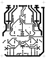
Bottom layout as well...for pcb .cheers")
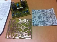
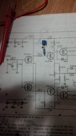
Well the pcb seems ok, BUT, the transistors from the predriver position needs to be BOTH of them connected with the emitors on the terminals of the 500 ohm trimpot. In your case one of them in conected proprely (the one from V-) but the other (from V+) is NOT. Beware for this aspect. Watch out at the assembly.
A second aspect wich is VERY important is that you have to reroute the traces coming from the 0.33r/6W (you case the 1R/2w resitors). You have to put somehow the resistors in a way, so that the V+ and V- coming from them is conected FIRST to the emitors of the drivers and them go to the collectors of the outputs. This is the main reason that my first pcb didnt work.
Look at my pcb from bellow.
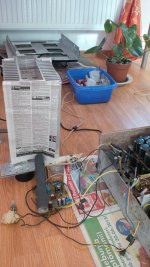
I also attached a pic an etched pcb of mine to see the thickness of my traces and the first test assembled pcb.
Cheers
Sergiu
Attachments
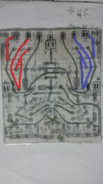
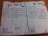
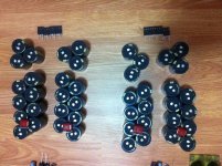
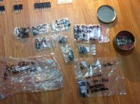
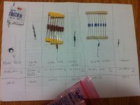
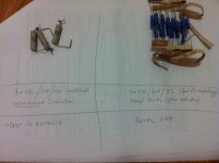
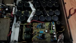
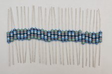
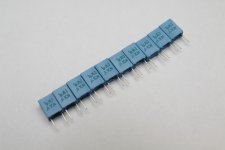
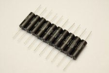
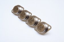
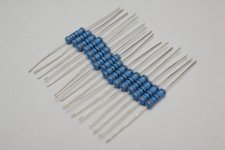
And here are some pics with the component sorting (transistors) and tests for 680ohm input resistors and the two types of output resistors that i have tested. And as you can see the amp is now working with 6 trafos..
Attachments
-
 IMG_2877.jpg705.4 KB · Views: 120
 -
 IMG_2860.jpg743.5 KB · Views: 142
 -
 IMG_2854.jpg828.6 KB · Views: 192
 -
 IMG_2880.jpg856.3 KB · Views: 88
 -
 IMG_3069.jpg582.7 KB · Views: 89
 -
 IMG_3070.jpg612.4 KB · Views: 85
 -
 IMG_20151020_184516.jpg421.7 KB · Views: 73
 -
 IMG_20150721_185947.jpg524.1 KB · Views: 64
 -
 IMG_20151020_214723.jpg578.4 KB · Views: 124
 -
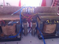 photo 3_1.JPG545.1 KB · Views: 114
Last edited:
And here are some pics with the component sorting (transistors) and tests for 680ohm input resistors and the two types of output resistors that i have tested. And as you can see the amp is now working with 6 trafos..
With 60EPU diodes soft start not needed.
And don't use china's PET caps (on 1st photo red caps), better to use Epcos MKT or MKP.
Last edited:
Hi saraswat,
So you have on your trafo four windings, summing two 20-0-20 v AC secondaries?
How much wattage has the trafo on the primary? Is it a 720~750va transformer E+I trafo? Because basically you would obtain an equivallent of two 300va @7.5 A in the secondaries trafos if i'm not mistaken wich would be very good..
Give us some more details please.
Separate trafos would be about 60% higher cost but in case of E+I they would be better tighten and work with lesser mechanical noise, and if bicafillary winded they can have the same impedance on each secondary like in the case of R core or C core. Also this sollution gives a better separation between the two channels BUT the psu will have higher costs overall (more caps, more diode bridges AND BIGGER CASE). Your choice here. If money isnt a problem i would sugest two trafos. Its worth it.
Cheers
Sergiu
Hi, Sergiu, it's a toroidal type not the E I type. There will be 4 outputs at secondary with 150 va each @ 20v.. If you suggest will go for 2 separate toroidals, with 2 outputs each I.e 2*20v 300va. What should be the primary wattage if secondary is at 300va? regards
With 60EPU diodes soft start not needed.
And don't use china's PET caps (on 1st photo red caps), better to use Epcos MKT or MKP.
I know but I was thinking how to prolongue the trafos's lifes... :d:d:d
To be honest I didnt think a second about them. The stupid seller from the local shop in my town recomended them to me(2.2uF/600v). Without seeing the producer written on them I thought they where some good quality caps but after hearing this from you now I want to kill that guy.
I cannot remove them right now. The case is bolted with screws now. I think I will change them in the next revision or overhaull of the amp...
Thanks for the tips.
Cheers
Sergiu
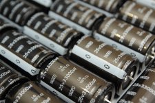
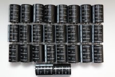
Yestarday I got caps for my small filter Hiraga's 20W 26*33000uFx25V.I know but I was thinking how to prolongue the trafos's lifes... :d:d:d
To be honest I didnt think a second about them. The stupid seller from the local shop in my town recomended them to me(2.2uF/600v). Without seeing the producer written on them I thought they where some good quality caps but after hearing this from you now I want to kill that guy.
I cannot remove them right now. The case is bolted with screws now. I think I will change them in the next revision or overhaull of the amp...
Thanks for the tips.
Cheers
Sergiu
Later will do photos.
Yestarday I got caps for my small filter Hiraga's 20W 26*33000uFx25V.
Later will do photos.
Nice. Looking forward to see your progress.
Cheers
Sergiu
Nice. Looking forward to see your progress.
Cheers
Sergiu
Very big and fast progress... in chattering.
Nice. Looking forward to see your progress.
Cheers
Sergiu
In process...
Attachments
-
 Hir20W 1979 006.JPG718.6 KB · Views: 138
 -
 Hir20W 1979 005.JPG522 KB · Views: 178
 -
 Hir20W 1979 004.JPG896.6 KB · Views: 179
 -
 Hir20W 1979 003.JPG971.9 KB · Views: 343
 -
 Hir20W 1979 002.JPG531.3 KB · Views: 371
 -
 Hir20W 1979 001.JPG417.4 KB · Views: 407
 -
 Hir20W ART 001.jpg483.8 KB · Views: 409
 -
 Hir20W 1979 007.JPG653.8 KB · Views: 134
Nice.
It will be nicely blow up.
0,858F in filter and 2*6800uF on each amp pcb.
- Status
- This old topic is closed. If you want to reopen this topic, contact a moderator using the "Report Post" button.
- Home
- Amplifiers
- Solid State
- Hiraga class a 30 w amplifier