Hi, can anybody please send a link or mention stepwise.. how to set the bias of Jean Hiraga 30watts super class A amplifier...thanks in advance.
Hi. As such bias can't be regulate, it depends from transistor types. If you use modern transistors (as example, 2sc4793, bc550cg and etc.) on resistor in collector will be drop, usually 0,55-0,7V. You can regulate bias by changing nominal value of the resistors (I recommending not bigger, than 0,5 om (10W minimum)).
Hi. As such bias can't be regulate, it depends from transistor types. If you use modern transistors (as example, 2sc4793, bc550cg and etc.) on resistor in collector will be drop, usually 0,55-0,7V. You can regulate bias by changing nominal value of the resistors (I recommending not bigger, than 0,5 om (10W minimum)).
I would not change outputs collector resistors but change instead those between VAS base and rails (usually 33K or 47K depending on the various schematics). Outputs bias can be regulated this way. For me 33K worked fine to obtain Class A bias. With 47K, bias was too low.
Cheers,
Jacques
I would not change outputs collector resistors but change instead those between VAS base and rails (usually 33K or 47K depending on the various schematics). Outputs bias can be regulated this way. For me 33K worked fine to obtain Class A bias. With 47K, bias was too low.
Cheers,
Jacques
I'd feared to touch to these resistors.
")
Hi, can anybody please send a link or mention stepwise.. how to set the bias of Jean Hiraga 30watts super class A amplifier...thanks in advance.
Hi saraswat,
Here you go, i described the bias adjust in the post from bellow:
http://www.diyaudio.com/forums/solid-state/193-hiraga-20w-class-78.html#post4245192
I hope this helps.
Cheers
Sergiu
Hi saraswat,
Here you go, i described the bias adjust in the post from bellow:
http://www.diyaudio.com/forums/solid-state/193-hiraga-20w-class-78.html#post4245192
I hope this helps.
Cheers
Sergiu
Hello Sergiu2009; many thanks for the link...will update when will start the testing...currently working on the pcb.
Have procured the following tran's for the driver and output stage. Pls suggest how these will work in the design.
1) BC 547B
BC 557B
BD 237
BD 238
2SA1943
2SC5200
2) Will be using dale resistors for signal stage and also all wima caps ,
3) Supply voltage. +-35V, 300va. Unregulated. Total caps @ 1.16F
4) Will be using 3 metal oxide 1R 2W, resistors in parallel for 0.33R 6W, also have wire wound 0.33R 5W as well , which one will be better?
5) Have made provisions for series / parallel connection of resistors on the pcb for matching.
6) I am not using the original pcb, and have traced a pcb myself. Do you suggest any basic guideline for component placement for low noise. Have modified a pcb trace found in the net for suiting my purpose and components widths.
7) In your thread you have not shared any pics of your construction...will be happy to see that. Pls share.
8) shall I put provisions on pcb for using trim pots for calibration side by side to the resistors mentioned in your thread...
Waiting for your suggestions....many thanks once again.
Kind regards.
Hello,
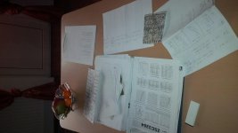
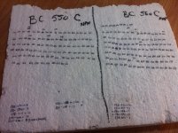
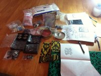
As you may see in the pic bellow I have a ton of findings written on paper about tests, diffrent components, arangements bias, and pcb from all the construction steps of this amp. I havent posted them yet because I waited for starting a new thread... I hope I will do that soon.
In this afternoon I will answer to your question. Now i'm out for shopping with my wife.
Cheers
Sergiu
Attachments
Hello Sergiu2009; many thanks for the link...will update when will start the testing...currently working on the pcb.
Have procured the following tran's for the driver and output stage. Pls suggest how these will work in the design.
1) BC 547B
BC 557B
BD 237
BD 238
2SA1943
2SC5200
2) Will be using dale resistors for signal stage and also all wima caps ,
3) Supply voltage. +-35V, 300va. Unregulated. Total caps @ 1.16F
4) Will be using 3 metal oxide 1R 2W, resistors in parallel for 0.33R 6W, also have wire wound 0.33R 5W as well , which one will be better?
5) Have made provisions for series / parallel connection of resistors on the pcb for matching.
6) I am not using the original pcb, and have traced a pcb myself. Do you suggest any basic guideline for component placement for low noise. Have modified a pcb trace found in the net for suiting my purpose and components widths.
7) In your thread you have not shared any pics of your construction...will be happy to see that. Pls share.
8) shall I put provisions on pcb for using trim pots for calibration side by side to the resistors mentioned in your thread...
Waiting for your suggestions....many thanks once again.
Kind regards.
Hi saraswat,
Here are my sugestions for you:
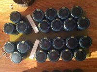
1) i sugest that you buy 100 pcs bc547b and bc557B because you have to match them within 1%, ensure that you have a reading between 500 and 550 (or, in you case Beta on you DMM. Be shure to match/measure them in the same day because even 1 degree celsius rome ambient will rise your readings and ruin everything.
Without knowing this important aspect I have measured them in two days and the results were catastrophicall, so I measured them again (i had 260 transistors BC550C/560C) in one day and noted them again. This operation will take you aprox 2-3 days to have two to three good pairs wich means a maximum of 16 bc 547b and 16 pcs bc557b (it differs from batch to batch).
First keep the transistors 6 secs in the DMM, then note the values and stick the trannies with the values close..
After this first step, when you have choosen the desired pairs measure them again, this time keep them for 12-20 secs till the Beta stabilises on the DMM.
This matching will ensure you very low distorsion at max volume and will help you adjust the ofset really easy.
The drivers BD237/BD238 are abit too slow and have low Beta and FT, but you can use them if you want, I have seen cases were they have worked.. I would sugest a higher Beta and FT transistors like 2sa1837/c4793 (these were best for me). But you can use any pair but with these aspects in mind: low Cob (max 35-40pf), high FT (70-100Mhz not more) and as much Beta you can.
The outputs are fine.
2) I tested aprox six types of resistors [carbon (Royal Ohm and ordinary China from the local store), metal film=two producers (Vishay & Royal Ohm) , metal oxide, power metal), BUT the best of all where in therms of stability and values disponibility the metal film ones. The best sound achieved was with The Vishay Dale on the input and Royal Ohm metal film for the rest.
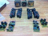
For the output resistor i would recomend 3x1ohm/3w paralelled metal oxide (or metal film)resistors per side (because this keeps the noise induced at low levels and keeps the barely warm==this is tested) and a total of 6 for both sides per one channel, because this gives a hell of allot better sound. If you will put fewer metal oxide resistors on these positions they will run reeeealy reeeeally hot (cant touch them) and will lower the lifespam.
Also i strongly advice you to use metal oxide or metal film resistors for the 1k8 resistors for bias at the base of the outputs two 3k6/2 or 3 w in parallel for each side/per channel This gives better stability and long lifespam for them. This way you can touch them..
For the rest of the resistors you can use metal film between 0.5 to 1w (watever producer you want) and max 100ppm for best stability in time.
I also used wima caps for bypass (MKT or MKP for the 2200pF for the output and 100nf) but used silver mica for the 68pF. Also styroflex will work here.
3) "Supply voltage. +-35V, 300va. Unregulated. Total caps @ 1.16F"
The total filtrage bank is ok BUT 300va is TOO LOW. If you you read the original 30w Hiraga article, 300va was sufficient only for 25v+25v@ 1.5A bias and was a dual C core transformer impregnated with a ceramic laqueur under vacuum, and has a very good randament and very low noise.
I would sugest two 300va trafos for standard or a max 27v+27v Ual and 1.65A bias (my case) because they allready run very hot in the summer (aprox 50 to 55 degrees celsius and sometimes 57) and bare in mind that they are custom made E+I laquer bathed.
If you want to make Dan's version of Hiraga (i spoke and asket him allot of questions when i made my amp and he helped me allot) amp from here Jean Hiraga's Super Class-A Amplifier I would sugest two 400va trafos or one 800va trafo because 500va as he used, will run really hot (he said this himself).
I have measured 38w sinus continous power at 8 ohm with +-27V@1.65A bias and cannot stay in my 25sqm room at max volume with 92dB speakers. Why need more? Keep in mind that Class A sounds higher than they are rated.
4) This has been answered at number two. The wirewound are almost all inductive, and i found in my listening tests that they do sound good but abit "unopened" and the voices are not so clear and instruments are not so whell defined. Also the soundstage wasnt so deep.
With the metal oxide resistors on this spot the amp was in another league; all of the above said where eliminated. Now the sound will make you hair raise on your spine. Extraordinary sound....
5) very good. You will need to perfectly match the resistors on both channels for not to hear any differences (buy 20pcs of each and you will manage this with ease).
I havent mention that you output transistor must be matched within 10%range (buy 10pcs of each and you will manage this with ease).
and the drivers max 5% range match (buy 10pcs of each and you will manage this with ease).
6)) "I am not using the original pcb, and have traced a pcb myself. Do you suggest any basic guideline for component placement for low noise. Have modified a pcb trace found in the net for suiting my purpose and components widths."
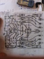
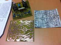
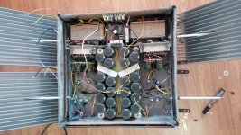
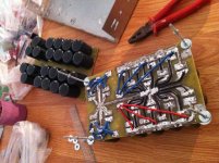
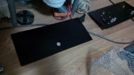
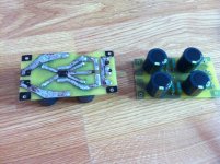
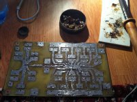
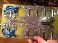
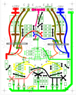
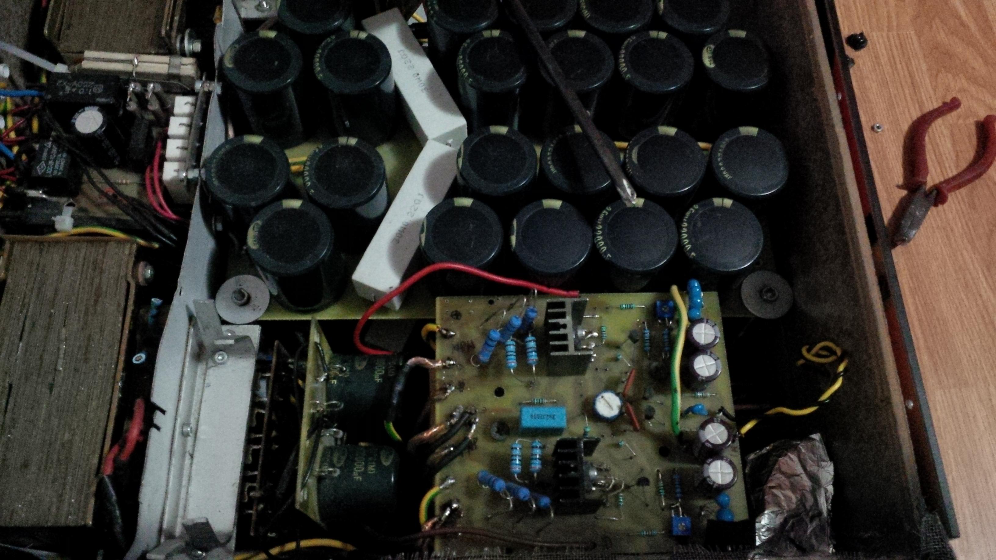
I would not recomend that you make one of youself unless you know perfectly how this topology works. I two made a PCB and wasnt able to adjust the bias lower than 2.5 amps with major modifications so use original pcb. In the firs pic attached is the pcb that i used. Its based on the original one but with some slight modification for the parts that i chosed.
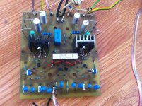
(see the third pic with the populated pcb). Note that the 68 pF caps are on the back of the pcb.
7) i want to open a thread with all of the tips and tricks and pics.
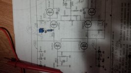
8) Yes you can make provisions, in position of the 33/47k bias resistors and for the 500 ohm offset adjustment trimpot.
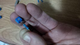
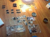
Speaking of trimpots, after alloot of study and searching on the net for the famous Cosmos RA12P originally used i found and now use this trimpot 3345P-1-501 BOURNS - Poten?iometru: de montare | TME - Componente electronice in series for match with two 10R/1w resistors and for the bias resistor I use this trimpot http://www.tme.eu/ro/Document/805f31775b95580e9350d5bab5cfcd98/3362.pdf and because its has carbon see in the catalog sheets that it "Withstands harsh environments and
immersion cleaning processes" type in series with a 2w /16k metal film resistor (see the fourth pic). You may also use a multiturn one in this position, they will allow you a finer adjust but you have to spin the scredriver abit for the desired bias ( i also used multitrun trimpot (see in the pics beelow) and didnt use now. These trimpots (the 500 ohm one) allows me to adjust the offset at a steady 5mV.
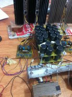
Also a big improvement is separating the left from righ psu (duall channel) and input from output psu (like my case), this also improves the soundstage and sound in a very good way.
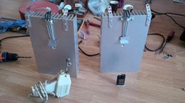
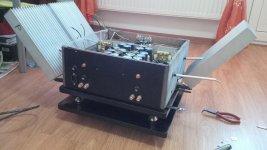
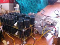
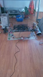
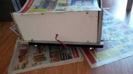
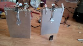
Also be carefull at the rads that you use. Things are going to get hot at 35v and 1.65 bias. I have seen that the increased bias makes the outputs run really hot... Just to see the comparison looke at the rads that i use now in the last pics...
Cheers
Sergiu
Attachments
-
 IMG_3030.jpg659.9 KB · Views: 781
 -
 IMG_20151122_170754.jpg599.3 KB · Views: 789
 -
 IMG_3037.jpg792.8 KB · Views: 733
 -
 IMG_3033.jpg759.5 KB · Views: 710
 -
 IMG_20151020_184516.jpg560.2 KB · Views: 241
 -
 IMG_20151020_184457.jpg535.1 KB · Views: 252
 -
 IMG_20151003_114126.jpg603.8 KB · Views: 205
 -
 IMG_20151003_105506.jpg712.6 KB · Views: 280
 -
 IMG_20151003_105535.jpg614.3 KB · Views: 283
Last edited:
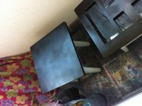
the finished product
Here it is. My amp, and the pcb populated with the trimpots mentioned in the above post.
Here it is. My amp, and the pcb populated with the trimpots mentioned in the above post.
Attachments
-
 IMG_20151020_214733.jpg617 KB · Views: 209
 -
 IMG_20151020_214723.jpg578.4 KB · Views: 268
 -
 IMG_2877.jpg705.4 KB · Views: 165
 -
 IMG_3040.jpg668.9 KB · Views: 183
 -
 IMG_2914.jpg812.2 KB · Views: 214
 -
 IMG_20150721_185938.jpg423.9 KB · Views: 180
 -
 IMG_20150826_194925.jpg530.4 KB · Views: 104
 -
 IMG_20150802_101144.jpg585.1 KB · Views: 138
 -
 IMG_20150826_194917.jpg605.9 KB · Views: 145
 -
 IMG_3177.jpg510.7 KB · Views: 105
some more pics
7) some more pics
7) some more pics
Attachments
-
 IMG_20151003_114101.jpg514.8 KB · Views: 111
 -
 IMG_20151003_114050.jpg523.3 KB · Views: 87
 -
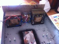 photo 1_1.JPG515.9 KB · Views: 76
 -
 photo 2.JPG467.9 KB · Views: 67
 -
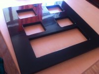 photo 1.JPG431 KB · Views: 83
 -
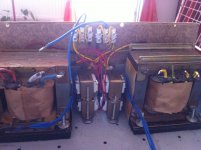 photo 3_1.JPG545.1 KB · Views: 90
 -
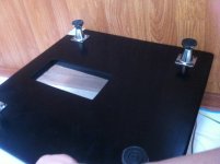 photo 5_1.JPG452.5 KB · Views: 77
 -
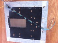 photo 4_1.JPG559.4 KB · Views: 63
 -
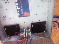 photo 5.JPG564.5 KB · Views: 90
 -
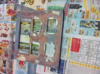 photo 3_2.JPG655.5 KB · Views: 123
pics 3
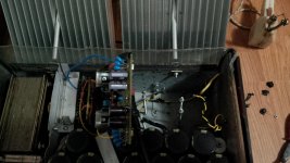
input psu+ soft start+ output psu
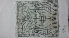
The second and forth pic is with my own designed pcb wich DIDNT work...
The rads from the last pic are the ones that i changed because they were too small.
input psu+ soft start+ output psu
The second and forth pic is with my own designed pcb wich DIDNT work...
The rads from the last pic are the ones that i changed because they were too small.
Attachments
-
 IMG_2825.jpg637.6 KB · Views: 117
 -
 IMG_2828.jpg890.8 KB · Views: 130
 -
 IMG_2831.jpg833.9 KB · Views: 122
 -
 IMG_2899.jpg696.3 KB · Views: 95
 -
 IMG_2879.jpg725.6 KB · Views: 113
 -
 IMG_2856.jpg835.5 KB · Views: 126
 -
 IMG_2901.jpg718.2 KB · Views: 128
 -
 IMG_2908.jpg730.4 KB · Views: 122
 -
 IMG_2989.jpg766.4 KB · Views: 144
 -
 IMG_3065.jpg728.7 KB · Views: 156
Last edited:

Hi, Sergiu, thanks for your support and answering all my questions in a very detailed manner. I am extremely delighted to see your builds, you have put in loads of effort for building this masterpiece amp. I will go by your suggestions and currently it seems i have to restructure my build again. As suggested will procure more pcs of transistors for close matching. Finding quality components and procuring them here at my place is a very big challenge and cost is very high.
Those blue caps on the amp board seems tantalum in parallel?? right. does it sounds better than nichicon (audio series )elctrolytics
1) Regarding the transformer can I use the current one for one channel and procure another with same specs. ( dual 25v 300va), or you suggest i go for a single transformer with lower voltage and higher current...say for example 18volts, 600va for getting ~ 25volts at output.
2) Can i be able to use the same output transistor ( 2sa1943 and 2sc5200) if i reduce the voltage to 25volts.
3) What was the reason for the failure of your board? was the layouting diffrent from the schematics or there was any other issue related to component placement. I have already spend 2 months in drawing the PCB in diptrace, I was about to fabricate the same tomorrow, i am scared now. I have throughly checked and the pcb layout is exactly as per the schematics of Jean Hiraga without any electrical errors. what do you say??.
I get very less time to spend on my hobby, i usually do it on my offday, most time i travel for my official work, this build is going to take a lot of time, I will be happy if you guide me to the end of the project.
Many thanks and looking forward to see your build thread, pls start it as soon as possible, as there are many builders around the world looking for detailed plans for construction.
Regards.
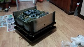
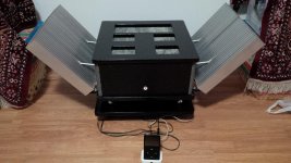
Looks like a mini NASA satellite...excellent work done. Those cooling fins are perfectly placed on open air....very different from other Hiraga modules built till date.
Also pls post a video of the same performing on youtube, and by the way , what speakers are you playing in with this amp.
Regards
Also pls post a video of the same performing on youtube, and by the way , what speakers are you playing in with this amp.
Regards
Last edited:
Looks like a mini NASA satellite...excellent work done. Those cooling fins are perfectly placed on open air....very different from other Hiraga modules built till date.
Also pls post a video of the same performing on youtube, and by the way , what speakers are you playing in with this amp.
Regards
Hi saraswat,
Thank you.
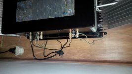
Yes those cooling fins are placed exactly at 45 degree and are insolated from the chasis. The transistors are bolted directly on the rads with Prolimatech sylver grease. After two weeks of tests i found that this is the perfect solution for colling the outputs (for Hiraga and other class A amps) and keeping the temp difference between the transistors and rads very low at 5 to 6 degrees celsius.
I will post a video but the cam on the phone is not so good..
Now i listen to a refurbished sealed 40w/8ohm and aprox 92 db Tento speakers from an old Kashtan mag. They are 30 years old, but i have rewinded the coils on mylar (they are lighter now) and changed and doubled the magnets with newer and more powerfull ones. The filters are all brand new and placed in the speakers after i measured the TS of the new speakers..
I'm planing to build this speaker https://www.google.ro/search?q=ruba...hXBkSwKHVZmCDcQ_AUIBigB#imgrc=3jTSCXuFM1xF5M: with a 15" papercone bass speaker.
The work in progress http://www.diyaudio.com/forums/plan...on-speaker-different-kind-46.html#post4519154 and http://www.diyaudio.com/forums/plan...on-speaker-different-kind-46.html#post4509348..
Cheers
Sergiu
Hi, Sergiu, thanks for your support and answering all my questions in a very detailed manner. I am extremely delighted to see your builds, you have put in loads of effort for building this masterpiece amp. I will go by your suggestions and currently it seems i have to restructure my build again. As suggested will procure more pcs of transistors for close matching. Finding quality components and procuring them here at my place is a very big challenge and cost is very high.
Those blue caps on the amp board seems tantalum in parallel?? right. does it sounds better than nichicon (audio series )elctrolytics
1) Regarding the transformer can I use the current one for one channel and procure another with same specs. ( dual 25v 300va), or you suggest i go for a single transformer with lower voltage and higher current...say for example 18volts, 600va for getting ~ 25volts at output.
2) Can i be able to use the same output transistor ( 2sa1943 and 2sc5200) if i reduce the voltage to 25volts.
3) What was the reason for the failure of your board? was the layouting diffrent from the schematics or there was any other issue related to component placement. I have already spend 2 months in drawing the PCB in diptrace, I was about to fabricate the same tomorrow, i am scared now. I have throughly checked and the pcb layout is exactly as per the schematics of Jean Hiraga without any electrical errors. what do you say??.
I get very less time to spend on my hobby, i usually do it on my offday, most time i travel for my official work, this build is going to take a lot of time, I will be happy if you guide me to the end of the project.
Many thanks and looking forward to see your build thread, pls start it as soon as possible, as there are many builders around the world looking for detailed plans for construction.
Regards.
Hi saraswat,
Thank you. It took me a year to complete my amp and tests. The problem with the components is the same here in Romania. I couldnt find at the local store original parts so i purchased them from TME and FARNELL. I found TME have better prices but Farnell has some more exotic components. What can i say, quality costs money and allot of time...
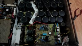
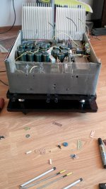
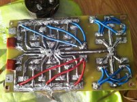
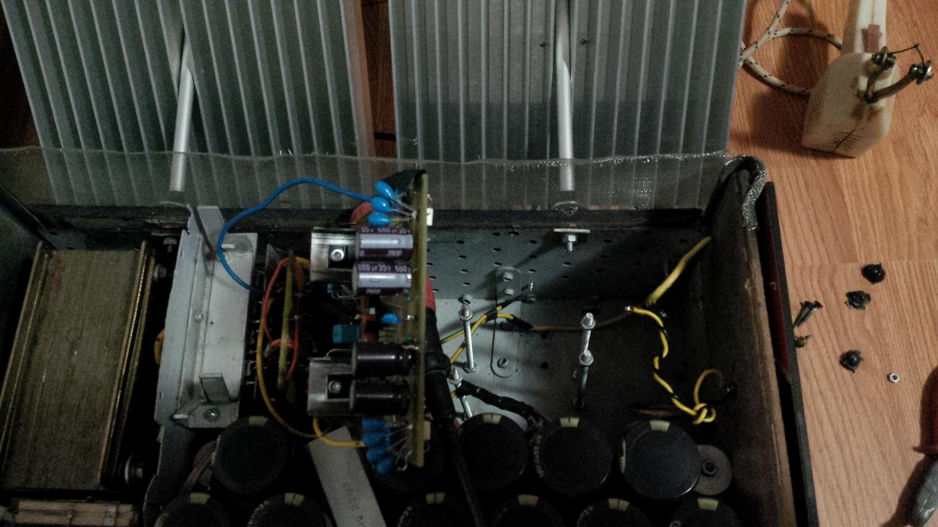
Yes the blue caps are tantalum, 15uF/35V and all of them are paired with the DMM to have the same value on each set of four (aprox 4*13uF/35v). The sound was very good but was lacking bass so i added 2* 680/35v low esr per side audio Nichicon caps (see the pics: http://www.diyaudio.com/forums/atta...-class-30-w-amplifier-img_20151020_214723.jpg and http://www.diyaudio.com/forums/atta...-class-30-w-amplifier-img_20151020_214733.jpg http://www.diyaudio.com/forums/solid-state/250761-hiraga-class-30-w-amplifier-3.html#post4525645 ). This added a deeper bass and a cleaner overall sound. So i sugest to do the same or go lower, say a min of 3x480uF/35v low esr and NOT tantalum. I kept them there because they where allready paired and soldered.
The tantalum ones have a very low esr and very good temp tolerance BUT they dont have much capacitance as you need if you use dual PSU (one per input and one per output) or dual mono like mine, or too long Ual cables.
1)Yes i would sugest to use one for one channel for now, and after the job is done use two, one for each channel. I would sugest this way from the start because this gives a better separation between the channels. I have tried a single trafo, but the sound in therms of sound stage wasnt so impressive. Dond get me wrong, it did sounded very good but not best. The best soundstage was with two trafos. With this combo the artists are like singing in front of you at 1 meter.
I would sugest if you want to save some money with the rads buy two 20-0-20 vac trafos at 6A@300va (or modifiy the ones that you have) to have a 25-0-25v cc and a standard 1.5A bias. This way the trafos will run cooler and the rads will be smaller. I dont like in case of the E+I trafos bigger ones because they tend to buzz allot if the core isnt fastened and laquered proprely.. The toroidals, R cores or double C cores trafos are in another league. I any of these cases if you use two trafos you can make a flatter case for the amp because the trafos are smaller..
2) Yes, you can use those transistors with no problems.
3) Well i did the same, but you should consider that this amp is based mostly on local NFB so the traces must be drawed accordingly. If you copy my pcb from here http://www.diyaudio.com/forums/atta...-class-30-w-amplifier-img_20151122_170754.jpg on a A4 matematic paper and use it and put the 68pF caps on the back of the PCB the amp will work from the start with no errors. Better do this now than be in trouble like i was for aprox two months because I couldnt adjust it. I had to redo a new pcb and etch again. So please keep this in mind.
"I get very less time to spend on my hobby, i usually do it on my offday, most time i travel for my official work, this build is going to take a lot of time, I will be happy if you guide me to the end of the project. "
I have too a job so it was tough for me too, and it took me a year. But be pacient. The results will surely amaze you. I will be happy to help you.
I know that i have to start a new thread. I have been through the pain of waiting for for the answers to come..
I want to start a thread to show others that this amp isnt as hard as it seems. If you match everything with care and make be carefull with the adjustments and pcb you will have an extraordinary amp at the end of the day.Cheers
Sergiu
Last edited:
Hi saraswat,
Thank you. It took me a year to complete my amp and tests. The problem with the components is the same here in Romania. I couldnt find at the local store original parts so i purchased them from TME and FARNELL. I found TME have better prices but Farnell has some more exotic components. What can i say, quality costs money and allot of time...
Yes the blue caps are tantalum, 15uF/35V and all of them are paired with the DMM to have the same value on each set of four (aprox 4*13uF/35v). The sound was very good but was lacking bass so i added 2* 680/35v low esr per side audio Nichicon caps (see the pics: http://www.diyaudio.com/forums/atta...-class-30-w-amplifier-img_20151020_214723.jpg and http://www.diyaudio.com/forums/atta...-class-30-w-amplifier-img_20151020_214733.jpg http://www.diyaudio.com/forums/solid-state/250761-hiraga-class-30-w-amplifier-3.html#post4525645 ). This added a deeper bass and a cleaner overall sound. So i sugest to do the same or go lower, say a min of 3x480uF/35v low esr and NOT tantalum. I kept them there because they where allready paired and soldered.
The tantalum ones have a very low esr and very good temp tolerance BUT they dont have much capacitance as you need if you use dual PSU (one per input and one per output) or dual mono like mine, or too long Ual cables.
1)Yes i would sugest to use one for one channel for now, and after the job is done use two, one for each channel. I would sugest this way from the start because this gives a better separation between the channels. I have tried a single trafo, but the sound in therms of sound stage wasnt so impressive. Dond get me wrong, it did sounded very good but not best. The best soundstage was with two trafos. With this combo the artists are like singing in front of you at 1 meter.
I would sugest if you want to save some money with the rads buy two 20-0-20 vac trafos at 6A@300va (or modifiy the ones that you have) to have a 25-0-25v cc and a standard 1.5A bias. This way the trafos will run cooler and the rads will be smaller. I dont like in case of the E+I trafos bigger ones because they tend to buzz allot if the core isnt fastened and laquered proprely.. The toroidals, R cores or double C cores trafos are in another league. I any of these cases if you use two trafos you can make a flatter case for the amp because the trafos are smaller..
2) Yes, you can use those transistors with no problems.
3) Well i did the same, but you should consider that this amp is based mostly on local NFB so the traces must be drawed accordingly. If you copy my pcb from here http://www.diyaudio.com/forums/atta...-class-30-w-amplifier-img_20151122_170754.jpg on a A4 matematic paper and use it and put the 68pF caps on the back of the PCB the amp will work from the start with no errors. Better do this now than be in trouble like i was for aprox two months because I couldnt adjust it. I had to redo a new pcb and etch again. So please keep this in mind.
"I get very less time to spend on my hobby, i usually do it on my offday, most time i travel for my official work, this build is going to take a lot of time, I will be happy if you guide me to the end of the project. "
I have too a job so it was tough for me too, and it took me a year. But be pacient. The results will surely amaze you. I will be happy to help you.
I know that i have to start a new thread. I have been through the pain of waiting for for the answers to come..
Cheers
Sergiu
I correct myself, the amp is based on local feedback, not NFB. It has low feedback. The topology is called emitor follower and the output is arranged in a darling-not topology if I remember exactly. Thanks Damon1983 for the pm. I shouldnt say eronate things. Sorry.
Cheers
Sergiu
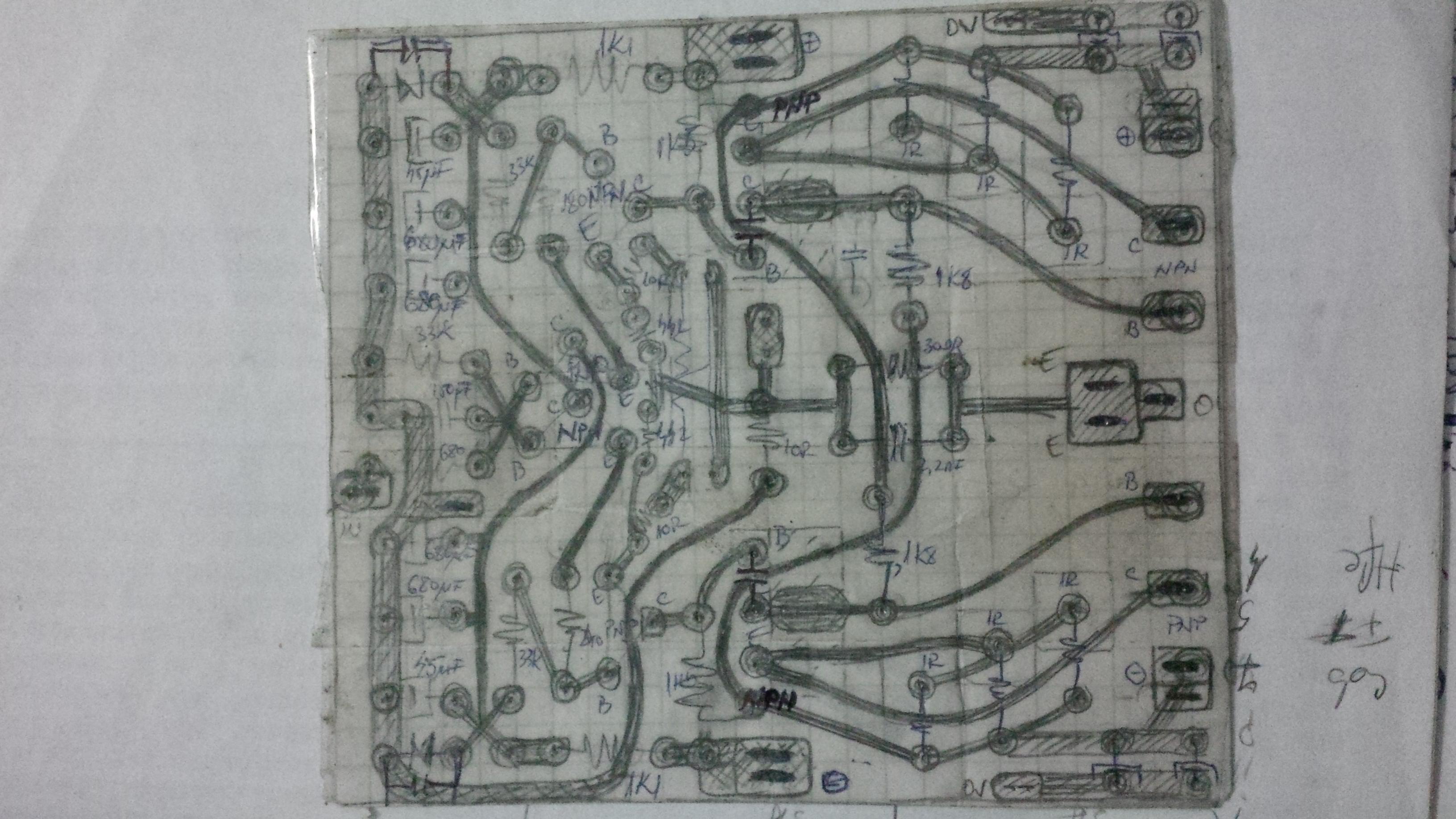
Hi, Sergiu, hope your are in best of spirits...I have redrawn a PCB for the amp and pls find the same here. Have sticked to the original board layout with modifications done for parallel and series combination of resistors to calibrate...I intended to use components readily available with me to get the desired values...Kindly check the same and suggest if its OK to go ahead. If you feel any further modifications to be done pls revert back...Thanks and Regards.
Hi, Sergiu, hope your are in best of spirits...I have redrawn a PCB for the amp and pls find the same here. Have sticked to the original board layout with modifications done for parallel and series combination of resistors to calibrate...I intended to use components readily available with me to get the desired values...Kindly check the same and suggest if its OK to go ahead. If you feel any further modifications to be done pls revert back...Thanks and Regards.
Hi saraswat,
Where is the pcb? Have you atached it?
Cheers
please find the PCB, couldnot upload due to connectivity issue...cheers
Hi saraswat,
Sorry for the late reply.
First:
1) why did you put 3* 300 ohm on the output instead of one. These dont get hot and the more you add in series the more noise you get. You can use only one 300ohm.
2) the 442 ohm resistors are in series. You dont want to do this because you will lower the bias... or you didnt find 442ohm resistors and want to put two resistors in series for that value?
3) No need for two resistor of 1k1 for the input polarisation. 2k2/1w is suficient.
4)the three 33k in series for the input are too much. Use a single 33k one.
5) I sugest to leave the 180/240 values intact for now. You will not need to modify them. So one space for one resistor is sufficient here.
6)for the 47k resistor you can make position for one 25k trimpot and one 33k resistor in series for bias adj and leave them there after the amp is done IF the trimpot is a quality sealed one or a fixed value resistor .
8) you will need thicker traces for V+ and - and also for the ground or bathsolder the ground trace as I did.
These are my first impressions. I will look again tomorrow to see if any other mistakes are made.
Cheers
Sergiu
- Status
- This old topic is closed. If you want to reopen this topic, contact a moderator using the "Report Post" button.
- Home
- Amplifiers
- Solid State
- Hiraga class a 30 w amplifier