Hi All,
FYI:
21SW005:21",1500W RMS, 3000W program,5" copper coil, neodymium subwoofer-hiwell
..But Use Qmd=16.5611429(MJK) for Driver TS Consistency
b🙂
Nice find.
Since OP didn't want to tell which drivers he has (unless I missed it somehow), here's a halfhearted quick sim.
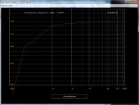
These drivers want about 400 or more liters each if you want a flat(ish) native response, and adding 300 g weight to raise qts is the opposite of a good idea. Here's what you can do with 400 liters total without (top) and with (bottom) a bit of eq. No iso loading required. Just a couple of peq filters and you get ruler flat down to 22 hz (if that's what you want) and you could extend the response lower than shown with ruler flat frequency response too (if that's what you want). Even without eq the response as shown would probably be ok once room gain and a nice fat room mode around 20 - 30 hz is added to the mix. Nice "tight" sealed box sound from a ported box but with a huge power handling and lower frequency output that a sealed box can't do. And easy as cake to eq flat as a ruler to as low as you want to go.
(The port is too small as shown, it should be larger and the eq'ed response is way past xmax but you get the idea. If OP can't be bothered to post t/s specs I'm not going to bother doing a proper sim - only just enough to prove that neither iso loading or adding weight to the cones is in any way necessary.)
An externally hosted image should be here but it was not working when we last tested it.
Last edited:
Ok Just, you vote NO on compound loading - I too have had just about enough of woofer frames sticking out into the listening space. They look awfully car-sound to me.
I've read about "6th order" alignments where the port tuning is a little lower and a little EQ is applied for lower F3. Wouldn't that PEQ blow through a lot of Xmax?
I've read about "6th order" alignments where the port tuning is a little lower and a little EQ is applied for lower F3. Wouldn't that PEQ blow through a lot of Xmax?
Wouldn't that PEQ blow through a lot of Xmax?
Absolutely it will. You don't get an extra 10 db at 20 hz (as shown) for free.
But consider the alternative - adding weight to the drivers increases the qts and makes the drivers want an even BIGGER box.
Iso loading cuts the box volume requirement in half BUT it effectively makes a single driver with 2x motor strength, which effectively cuts your driver displacement in half, which is a lot more lossy than using peq to boost the low frequencies. The peq doesn't have any losses, you just trade excursion for low end spl. If you sim the two different approaches the iso approach won't have the output you can achieve with a normal alignment regardless of eq.
Also, just to be clear, I simulated a super simple ported box, not a 6th order. Putting the drivers in a manifold would make it a 6th order, and you will likely use slot chambers unless you bottom fire the drivers (cones firing downward, not baskets hanging out the bottom) or fire out the backside and I could sim the response of a manifold too, although the manifold will eat up quite a bit of space.
Last edited:
Okay, let me sit and stare slack-jawed....
If that's what you want to do have fun. I prefer to do sims. In this case I just wanted to confirm the things I'm telling you for myself, and since I did them anyway I might as well show them. (The port is still way undersized in these sims but whatever.)
All sims shown in a 400 liter box with varying power levels and varying high pass filter settings. Box tuning is the same for all sims (box and port dimensions never change) and it's right around 20 hz as you can see by the dip in the excursion curve.
Row 1 - frequency response and excursion of normal mounting (no manifold, no iso load) with 2 drivers with (red) and without (blue) 2 peq filters, eq used to achieve a "max flat" response
Row 2 - same thing but with drivers iso loaded (no manifold)
Row 3 - same thing as row 2 but with drivers iso loaded and 300 g added to each driver (no manifold)
An externally hosted image should be here but it was not working when we last tested it.
For the added weight calculations here are my calculations:
Mmd = 283.55
Added mass = 300
m' = 583.55
mass ratio = 2.06
IIRC number to exponent 0.5 = number's square root, therefore:
mass ratio^0.5 = sqaure root of mass ratio, therefore:
mass ratio = 1.43, therefore:
Fs' = 17.48
Qes' = 0.49
Qms' = 23.68
These calculations gave me Mmd a bit higher than I was expecting so they might not be perfectly accurate but they should be close enough.
As you can see from looking at the graphs, the normal (non iso) loading gives almost 5 db more at the low knee than either of the normal or weighted iso alignments within the limits of xmax.
The non weighted iso alignment (Row 2) gives a nice flat(ish) response with no need for eq but max potential spl is nowhere near as loud as a normal alignment (Row 1).
The weighted iso alignment is just a bad idea all round. The frequency response is terrible, there's nowhere near the spl potential of a normal alignment (Row 1) and it's unclear if the driver is going to be happy pushing almost 600 grams of weight.
Please go ahead and redo these sims for yourself to confirm my results or point out any errors I may have made if you get bored with slack jawed staring.
I want to add as much as 300 grams to the cone.
Remember that? The Mmd is 283.55 grams. Add 300 grams to that and you get ...
Regardless, even if you add no mass, the normal alignment (Row 1) outperforms the iso alignment (Row 2) by a significant margin.
If the woofers are rear firing, wouldn't moving the enclosure close to the wall help low end extension?
As far as the drivers alone are concerned, it could create a type of hybrid bandpass if it was very close to the wall, but that will likely affect higher frequencies. As long as the distance from driver to boundary is within a 1/4 wavelength at the top of the passband you are already getting full boundary reinforcement. You just want to make sure the cancellation caused by the distance from driver to boundary doesn't cause the first big notch in response to be within the sub's passband. You can use Bagby's Diffraction and Boundary Simulator for that.
So as long as you are within 1/4 wavelength it doesn't matter too much where the drivers are - the top, the bottom, the sides, even the front might be close enough to the rear wall to get full boundary reinforcement.
Now the port is a different story. If it's on the bottom or back, and it's close enough to the boundary (the floor or the wall), that can increase the effective length of the port and tune the box lower.
In this example I used Bagby's software to simulate the effect of a single boundary. (I set the baffle size to infinite - or close enough - so that the diffraction profile is a flat line and has no effect except for a constant 6 db of gain through the entire passband. Then I set two of the boundary distances an infinite distance - or close enough - from the drivers so that those two boundaries would have no effect on the passband.)
What you see here is the effect of placing the drivers 6 inches from a single boundary (left) and 24 inches from the boundary (right). Doesn't matter if this boundary is the floor or the rear wall.
With 6 inches distance there's full 6 db boundary gain across the whole passband of a subwoofer. With 24 inches distance the reflection cancellation is getting low enough in frequency to have a minor impact on the top of a sub's passband.
Unfortunately there's no way to know exactly how much the boundary distance would affect the port tuning, that's not so easy to sim. You can guess but it won't be a huge effect as long as the distance is at least 1 port diameter distance away.
Hornresp will sim kinda the same thing if you do 1 pi space radiation instead of 2 pi, but it just gives a flat 5 - 6 db gain across the entire passband (which means the driver is functionally flush with the boundary, in other words flush mounted in the wall) so you won't get the notch in response corresponding to the reflection distance or the lower spl (non boundary reinforced) at higher frequencies.
What you see here is the effect of placing the drivers 6 inches from a single boundary (left) and 24 inches from the boundary (right). Doesn't matter if this boundary is the floor or the rear wall.
With 6 inches distance there's full 6 db boundary gain across the whole passband of a subwoofer. With 24 inches distance the reflection cancellation is getting low enough in frequency to have a minor impact on the top of a sub's passband.
Unfortunately there's no way to know exactly how much the boundary distance would affect the port tuning, that's not so easy to sim. You can guess but it won't be a huge effect as long as the distance is at least 1 port diameter distance away.
An externally hosted image should be here but it was not working when we last tested it.
Hornresp will sim kinda the same thing if you do 1 pi space radiation instead of 2 pi, but it just gives a flat 5 - 6 db gain across the entire passband (which means the driver is functionally flush with the boundary, in other words flush mounted in the wall) so you won't get the notch in response corresponding to the reflection distance or the lower spl (non boundary reinforced) at higher frequencies.
Last edited:
If the woofers are rear firing, wouldn't moving the enclosure close to the wall help low end extension?
Face,
The woofers in my brainstorm design face the rear but move air push-pull through a tunnel that would be covered. The rear would show only plywood. The one driver would sound out the bottom. To Just's point, at these wavelengths the deep bass would be reinforced and have to be EQ'd down. A nice shelf vent wouldn't clash with the lines of the cabinet...
To Just's point, at these wavelengths the deep bass would be reinforced and have to be EQ'd down.
If the drivers are free firing out the back (not in a tunnel) and within 6 inches of the wall, the boundary gain from the wall will be ~ equal across the whole passband of the sub, as i showed in the boundary sim a couple of posts ago.
Besides, if you don't add weight or do iso loading you will get dramatically more spl potential and the deep bass could use a boost, not a cut.
Just,
Hey, on post 14 is what I just called the tunnel what you call the manifold?
Yes, if you are referring to the thing at the bottom of your drawing. But your tunnel seems to be closed so it's more like a box. A tunnel that's open at one end will provide a pretty severe resonance at the top of your passband (or just above the passband) and you should simulate that effect. Also, depending on how the drivers are mounted in the tunnel and which end is open, there might be vastly unequal pressures on the cones, they could have very different excursion levels at different frequencies, and they could produce very different frequency response. Ricci (the data-bass guy) wrote about this extensively in his writeup for his MAUL project on the data-bass forum. You need Akabak to simulate that effect properly unless the drivers are equidistant from the tunnel opening.
Last edited:
Isobaric with 200g added to Each Woofer
Who needs brains when you have calculators? Using mh-audio.nl added-mass calculator, we get:
Calculated new Parameters, 200g added
Mass-Factor: 1.61
SPL loss: dB (1 W/1 m) 4.15 (minus another 3 if wired in series)
new fs: Hz 19.7
new Qts: 0.43
new SPL: dB (1 W/1 m) 92.15 (89 if I'm lucky)
Same site, vented box calculator (do these assume Ql of 7?)
Volume Vb = 403.26 liters
Fb = 17.68 Hz
Peak = 0.100 db
F-3 = 16.69 Hz
Attachments
I absolutely would not use the simulator on that site. If you are planning to use tunnels you absolutely need Hornresp or similar to get an accurate sim, and if the drivers are not equidistant from the tunnel exit you need Akabak.
And as I mentioned, there's absolutely no reason to add weight. This raises qts and your box is already on the small size (assuming you don't do iso, which you shouldn't, IMO).
And as I mentioned, there's absolutely no reason to add weight. This raises qts and your box is already on the small size (assuming you don't do iso, which you shouldn't, IMO).
If I can get this thing to belch bass down to 16 Hz and not vibrate like an unbalanced wash load, then it seems like a gentler parametric EQ curve would be needed to counteract the boundary boost.
Just, if I configure these per your simulations the cops might come knocking!
Just, if I configure these per your simulations the cops might come knocking!
- Status
- Not open for further replies.
- Home
- Loudspeakers
- Subwoofers
- High Wf Large Subwoofer