I was planning to build standard PSU with chokes and RC filters but changing the voltage is a pain. Does anyone can recommend a quality plate voltage power supply ready made or a kit for SE power amp with at least 300-320V and 60-70mA or more, preferably in Europe? Soft start, good PSRR, stabilized, low output impedance etc... I was looking on eBay but found only with low current for preamps.
In that voltage range you might be able to score a used electrophoresis power supply. Pharmacia European manufacturer.
Thank you for your reply, I was thinking about regulated module kit that I could use in an amplifier rather than laboratory power supply 🙂
I was planning to build standard PSU with chokes and RC filters but changing the voltage is a pain. Does anyone can recommend a quality plate voltage power supply ready made or a kit for SE power amp with at least 300-320V and 60-70mA or more, preferably in Europe? Soft start, good PSRR, stabilized, low output impedance etc... I was looking on eBay but found only with low current for preamps.
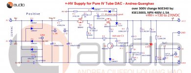
i think this design may be you can use!
low noise, low z-out, the sound is good!
thank your advice!
quanghao
Attachments
Thank you quangha, it is what I am looking for, high voltage regulator. Do you know if it exists as a ready made module I can buy somewhere?
You could use a 12VDC supply that runs a switchmode inverter to get 300VDC (ebay style 150W inverter). An RC buffer filter and you have a low impedance, stabilised supply with very low ripple.
What will happen if the load is reduced or the power is interrupted, or the tubes fail. Some of the power supply will over dissipate power.
A lab power supply is awesome. Some company makes suitable ones for tube amps.
A lab power supply is awesome. Some company makes suitable ones for tube amps.
For the example scheme I referred to, a shorted or overload on the B+ can be managed by using a 12VDC supply that has an over-current foldback limit of some kind, and then the following switchmode controller will typically hiccup as it enters/exits UVLO - that provides a good form of fault 'annunciation' 🙂
I am currently assembling the nuts and bolts to a 60W dissipation power supply for stereo.
So far the amp power supply has 1x 3 poles relays for the mains power (neutral and live) and for shunting the power supply output in case of tube failure or lack of conductivity to prevent dissipation, one for caps charging 'soft' start, one to cut power supply if the bias exceeds 3x value, 1 for shutting the bias monitoring circuit.
So instead of fusing each 4 anodes, I fuse the main transformer output and the regulated supply just before regulation.
The main idea with the bias monitoring and leds signals is to ensure bias within 2mA to use a toroidal transformer for approx. 50watts, UL with cathode feedback.
Thank you quangha, it is what I am looking for, high voltage regulator. Do you know if it exists as a ready made module I can buy somewhere?
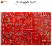
Hi this PCB
ans see information in this link: DAC ES9038 PRO GR 2
thanks
Attachments
I think this, is what you are looking for : HIGH VOLTAGE SUPPLY - ALIMENTATION HAUTE TENSION 0 / 300V - 0/150mA | eBay
Thank you Dieter.
I have created simulation of the schematics provided by Quanghao. The ripple rejection is impressive, especially with IRF840, they are great as a source follower, much better than STP5NK50Z I was using before. I have designed PCB and now I'm waiting for the boards 🙂

My only concerns is that it uses feedback and I am not sure how it can impact the sound.
Alternatively I will use this:

I have created simulation of the schematics provided by Quanghao. The ripple rejection is impressive, especially with IRF840, they are great as a source follower, much better than STP5NK50Z I was using before. I have designed PCB and now I'm waiting for the boards 🙂
My only concerns is that it uses feedback and I am not sure how it can impact the sound.
Alternatively I will use this:
Last edited:
Hi Ripson, this PSU is exactly I am looking for for my headphone AMP. How much output current it can made?
Hi Jerry Long,
I haven't finished PSU designed by quanghao and this is actually question for him, however on the simulation I checked 100mA and it was working great. I needed 300V output and I noticed that best results I got when input was 400V DC.
The second schematics also works fine at 100mA, but you need a heatsink for the mosfet. By changing CCS current (R13) you can regulate output voltage. This doesn't use feedback and the output impedance is higher. Hope that helps.
Attachments
Thanks Ripson, I want 220V/130mA for my headphone amp, is it possible to change some components to meet my need?
I thought Jfet css will be good for my need, since you have made it into PCB😉
I had used a PSU circuit successfully in my pre-amp, I change some components to meet the need of my headphone-amp but failed, so I want to find another PUS
http://www.diyaudio.com/forums/power-supplies/321216-help-psu-headphone-amp.html#post5399513
I had used a PSU circuit successfully in my pre-amp, I change some components to meet the need of my headphone-amp but failed, so I want to find another PUS
http://www.diyaudio.com/forums/power-supplies/321216-help-psu-headphone-amp.html#post5399513
I think the best person to help is Quanghao. You can try to send PM to him.I thought Jfet css will be good for my need, since you have made it into PCB😉
IMO there is not a lot of things to change, by changing the value of VR1 you can adjust the output voltage. You need to make sure the heatsink for Q2 is big enough, depending on the voltage drop between mosfet drain and source, and also the output current (Ohm law will help), something like 5-8 K/W should be fine, just keep it below 60-70 Celsius degree. Also R3 needs to have enough power rating depending on the output current, you might need to decrease the value of it if the output current is higher.
My PCB suits transformer with tapped winding in the center, so there are two rectifiers not four like in the Graetz bridge.
Thank you Dieter.
I have created simulation of the schematics provided by Quanghao. The ripple rejection is impressive, especially with IRF840, they are great as a source follower, much better than STP5NK50Z I was using before. I have designed PCB and now I'm waiting for the boards 🙂
this design the sound not the best!
thanks
- Home
- Amplifiers
- Power Supplies
- High voltage power supply module