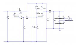
After 2 years I have finally completed the PSU. It has really low noise, from my calculations about 11 Ohms output impedance (much higher than in LTSpice simulations - not sure why). Instead of MJE340 I have used ST13005, instead of 2SK170 I have used 2sk163L, instead of 100uF I have used two 220uF/500V. The choke has 20H and 470 Ohms DC resistance. Under the PCB I have added temporarly extra 470k resistor that discharges the capacitors.
There is one problem with the output voltage. I believe it is related to JFET CCSs, when it starts operating the output voltage rises slowly from 295V to 310V, because the JFET temperature rises and the Id in the Jfets too.


There is one problem with the output voltage. I believe it is related to JFET CCSs, when it starts operating the output voltage rises slowly from 295V to 310V, because the JFET temperature rises and the Id in the Jfets too.
Last edited:

There is one problem with the output voltage. I believe it is related to JFET CCSs, when it starts operating the output voltage rises slowly from 295V to 310V, because the JFET temperature rises and the Id in the Jfets too.
You have two current sources.
Substitute a DC source for each of the JFETs in turn and in simulation (Temperature sweep) see if one or the other is having a more profound effect.
For low output impedance you'd require a complete rethink -- you need negative feedback.
Last edited:
Thank you for that 🙂
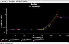
In the LTSpice simulation Zout is 0.11Ohm, measured is 11 Ohm - 100 times more.
As per sugestion of the author of this circuit of not using this cap I have not added one... well if I am not mistaken this is a Miller capacitor, so it seems this PSU is now prone to oscillation. I wanted to add it earlier and see what happen but I don't have any cap with such high voltage, I hope when I add one the output impedance will drop below 1 Ohm. I have added space for it on PCB anyway 🙂
Last edited:
That simulation was run with Multisim instead of LTSpice as the latter wasn't happy with the IRF840 model.
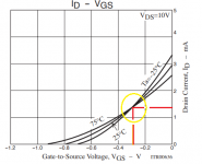
Data sheets for JFETs don't seem to include the gm vs temperature anymore. (see Erno Borbely's "JFETs the New Frontier" which is archived all over the web) it is interesting to note that if you use lower Idss JFETs there are better chances you can achieve something close to zero tempco. without the data it's a matter of trial and measurement. Lower JFET current also reduces self-heating.
Data sheets for JFETs don't seem to include the gm vs temperature anymore. (see Erno Borbely's "JFETs the New Frontier" which is archived all over the web) it is interesting to note that if you use lower Idss JFETs there are better chances you can achieve something close to zero tempco. without the data it's a matter of trial and measurement. Lower JFET current also reduces self-heating.
...and this is exactly what I read yesterday in document Bartola Gyrator Build Guide rev07 by Ale Moglia about keeping Id in LND150 (TO92) below 1mA to avoid temperature drift 🙂
I am going to play with R6 and C3 using some low Idss jfets and see what is going to happen.
I am going to play with R6 and C3 using some low Idss jfets and see what is going to happen.
I have found 330pF/500 mica cap and after soldering it to PCB I measured the Zout, it's 9.71 Ohm :/ Not sure if replacing the MOSFETs by different type might help here.
I measured the Zout, it's 9.71 Ohm :/ Not sure if replacing the MOSFETs by different type might help here.
I developed an easy method for measurement of Z-out -- A low Ciss Depletion Mosfet current is set by a resistor per normal. The gate is modulated with a sweep oscillator. These new-ish DMos from IXYS will only stand off a few hundred mA, so I set the DC current at 25mA.
for stability measurement you need to go to several MHz which may not be possible in your case. that's where it's handy to have Multisim or LTSpice, or Texas Instruments freeware version of pSpice.
Attachments
nice, thank you. it won't be "regulated" anymore, but it is a solution, first I would like to decrease the current to about 600uA changing R6 from 100k to 470k and see how much it will drift.
This is not my desing, only the PCB, 2 years ago I have got the circuit schamatics here on this thread from Quang Hao, the PSU was designed by Andrea Ciuffoli, Quang Hao and Morten Becker.
This is not my desing, only the PCB, 2 years ago I have got the circuit schamatics here on this thread from Quang Hao, the PSU was designed by Andrea Ciuffoli, Quang Hao and Morten Becker.
Last edited:
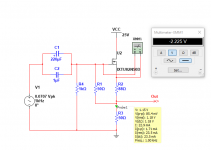
The simpliest possible method:
Uout - voltage measured without load
Uload - voltage measured with known load (Rload)
Rload - 22.4k resistor (4 x 5.6k/2W in series)
Rout = Rload * (Uout/Uload - 1)
Below is the output voltage with variable load from the simulation: 34mA DC + 17mA (amplitude) sine 50Hz - second plot.
It works great in a simulation, something is wong in real world 🙂


Variable load:

...and here if i am not mistaken is the Zout:

Uout - voltage measured without load
Uload - voltage measured with known load (Rload)
Rload - 22.4k resistor (4 x 5.6k/2W in series)
Rout = Rload * (Uout/Uload - 1)
Below is the output voltage with variable load from the simulation: 34mA DC + 17mA (amplitude) sine 50Hz - second plot.
It works great in a simulation, something is wong in real world 🙂
Variable load:
...and here if i am not mistaken is the Zout:
Last edited:

OK, when I decreased the Id current on CCS, Zout increased drastically, it also changed the NPN base current. I used BJT with a small hfe, the smallest possible, group A. I'm pretty sure that changing to different BJT with a higher DC gain will bring the PSU back to work withing the normal parameters 🙂

in the meanwhile...


I have replaced BJT with MOSFET, the output impedance is really small, I have replaced 2sk170BL with 2sk117GR (Idss around 4mA), the output voltage drift is much smaller.
I can't see any difference in output voltage with my voltage meter when I add 22.4k load, 13.4mA, 4W
So... is anything wrong in replacing bjt with mosfet here? So far it works really good... at least in simultion and with dc in real world 🙂
Last edited:
- Home
- Amplifiers
- Power Supplies
- High voltage power supply module