hello
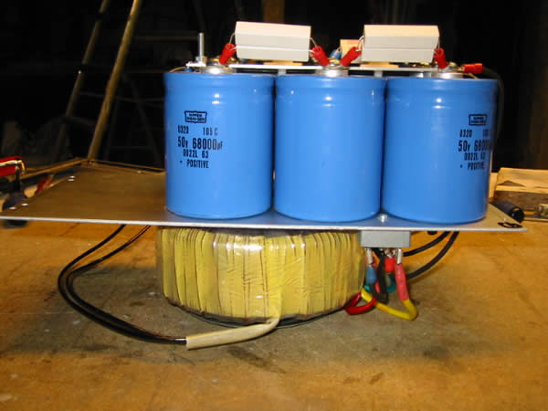
my power supply for a aleph 5 : CRCRC
for a mono block
2 x 30 V, 500 VA
2 bridges
R = 0.5 ohm
6 x 68000µF/50v
the nominal voltage is 34V
I obtain a tension of 42.5V, as in the books! (the amplifier board is not connected )
I connect or not 🙁
I don't like smoke
the tension should fall... but is this sufficient?
many aleph 5 were built with transformers of 2 X 30 v
how do they make?
thank you
Phill
http://domainedupossible.free.fr/pagemus/ALEPH5/aleph51.htm
Since your transformer is 500VA, it can supply up to 8.3A.
With 42V on the supply rail and 4A biasing, you could have up to 95W into 8ohms and 128W into 4ohms with 50% current gain.
With the Aleph5 you built using 6 output devices, each output device is dissipating 56W. Not good, you need at least 12 output devices to bring the power dissipation down to under 30W.
Just make sure you have sufficient output devices with enough heatsinking to keep the junction temperature of the devices low and the heatsink temperature less than 70°C.
Alternatively, you should reduce the voltage rails to make a lower power version.
Nothing should smoke if you wired up the board and outputs correctly.
hello
I can regulate the bias with R19, 2 A ==> 76W/9.5ohm end 28W dissipation/fet...or less if necessary
for the moment, I risk only one problem of dissipation...? it is that?
end the 3 capacitors 220µF/35v????
Thanks
Phill
I can regulate the bias with R19, 2 A ==> 76W/9.5ohm end 28W dissipation/fet...or less if necessary
for the moment, I risk only one problem of dissipation...? it is that?
end the 3 capacitors 220µF/35v????
Thanks
Phill
With 4A bias and the 0.5 Ohm resistors in the CRCRC you should also loose another 4V per rail when connected.
You should not worry about the 220/35 C's, these will never see this voltage.
Please correct me if mistaken.
You should not worry about the 220/35 C's, these will never see this voltage.
Please correct me if mistaken.
Phill said:hello
my power supply for a aleph 5 : CRCRC
for a mono block
2 x 30 V, 500 VA
2 bridges
R = 0.5 ohm
6 x 68000µF/50v
the nominal voltage is 34V
I obtain a tension of 42.5V, as in the books! (the amplifier board is not connected )
I connect or not 🙁
I don't like smoke
the tension should fall... but is this sufficient?
many aleph 5 were built with transformers of 2 X 30 v
how do they make?
thank you
Phill
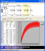
According to PSUD you should be just fine.
Attachments
hello
I connected a board amplifier
tension aux rails : +/- 38.8 v
tension Z5 : 9.08V
R11 : 5.36 v
R14 : 4.42 v
VgsQ1 : 3.64v
VgsQ2 : 3.64v
VgsQ4 : 3.74 v
resistances fet + : 626,652,610mv
resistances fet - : 634,632,625mv
Is the matching good ???
offset 11mv
that heats!
the second board does not function!
I must find the breakdown 🙄
Phill
hello there i have also 2 torroids of 2 X 30 Volt but i'am still working on the case
for more pic's photo album
for now i will first use 2 x 47.000 uF 50V elco's maybe later i will put some nice CLC or CRC filter in it. But for all i know is that i can use 6 diveces (FET's) per channel i still did not build them in my case. is it better to put some extra ?? and must i make some changes to the origenal aleph 5 design ??
gr Jaac
An externally hosted image should be here but it was not working when we last tested it.
for more pic's photo album
for now i will first use 2 x 47.000 uF 50V elco's maybe later i will put some nice CLC or CRC filter in it. But for all i know is that i can use 6 diveces (FET's) per channel i still did not build them in my case. is it better to put some extra ?? and must i make some changes to the origenal aleph 5 design ??
gr Jaac
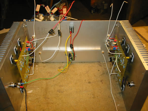
Jaac, a word of advice.
Do not use the mounting bolt of the trafo to mount anything else but the trafo. I fail to remember whom did that a while ago, but he had a lot of problems from it. He grounded the sheilding plate as well, in itself not a bad idea, but when mounted on top of the trafo you get a shorted turn on the trafo.....and lots of heat (and with patience some smoke and a bit of fireworks as well).
Magura 🙂
Magura said:Jaac, a word of advice.
Do not use the mounting bolt of the trafo to mount anything else but the trafo. I fail to remember whom did that a while ago, but he had a lot of problems from it. He grounded the sheilding plate as well, in itself not a bad idea, but when mounted on top of the trafo you get a shorted turn on the trafo.....and lots of heat (and with patience some smoke and a bit of fireworks as well).
Magura 🙂
but the bolt i use is made from stainles steel does that make any diverence ?? i hope so. at mi work we have a philips stabilisor it have some big trafo's in it the case its in is 3/4 steel and 1/4 ( the back panel) made of stainless steel to undone that shorted turn of the trafo. so i tought a stainless steel bolt will prefent that i hope.
As long as the bolt is conductive, it makes zip difference.
Simply keep that bolt away from anything but the trafo.
Magura 🙂
Simply keep that bolt away from anything but the trafo.
Magura 🙂
The simple work-around is to mount the PCB on standoffs, or attach it to the heatsinks. I would also move it away from the trafo. Active devices close to a trafo have caused me a lot of trouble in the past, especially with big trafos.
Magura 🙂
Magura 🙂
Jaac TheMaster
congratulation for your work
true work of professional !!!
good luck for the continuation
(have you a photograph of the back of the pcb? )
Phill
small handyman
congratulation for your work
true work of professional !!!
good luck for the continuation
(have you a photograph of the back of the pcb? )
Phill
small handyman
high frequency problem
Hello,
I made an aleph 5 and I have a problem with bandwith, from 10hz to 5khz no problem I achived 22v rms 8ohm load with 36v rail, but from 10khz to 20khz, it seems i have a distortion problem, i have only 10v output rms before positive region made a spike, I try to remove the 47n cap and I can correct the wave but in the x axle is not perfect as I want. But at 4 ohms I could not have more than 7v rms . what could be the problem (Sorry my english)
offset: 8 mV
4 x 47000uf caps
+/-36V rail
+/- 0,5V at 1 ohm resistor for each mosfet.
Thanks
What does the spike look like? Can you see it clearly with a
scode, or do you need a distortion analyzer to see it?
😎
scode, or do you need a distortion analyzer to see it?
😎
I can see it at in my scope, this is a strange thing, the voltages are all right, I have to send a pic to everybody see what I am talking about, if i increase the bias the figure disaper, but i must increase it closely to 0,68v across resistor (680ma) with 36V rail,(24W per fet) I have 4 mosfets not 3, honestly Iam figuring that is not a bias problem, because from 10Hz to 5khz, with 500ma per fet I have 22V rms before clip (8ohms) and 20v rms (4ohms), when increase the high frequency, the clip comes at 12 V rms (8 ohm load) and 7v rms (4 ohm load).
Any thoughts?
Any thoughts?
Nelson Pass said:What does the spike look like? Can you see it clearly with a
scode, or do you need a distortion analyzer to see it?
😎
what is "scode" ?

- Status
- Not open for further replies.
- Home
- Amplifiers
- Pass Labs
- high voltage on aleph 5