


it looks rough but hopeefully it will work 🙂


I think the project may not be interesting. If the moderators think I am bumping a useless thread I can stop posting.
Here is the results from anlysis of PSU requirements and board configurations..
voltages supplied:
1. +500v
2. +300v
3. +150v
4. +1600v
5. +600v
6. -150v
7. -300v
1. 500v
866A in full wave. Choke loaded: 5H 53ohms. 235uf
suggested: 500v CT
2. +300v
866A in full wave. Choke loaded 5H 53 ohms 470uf
suggested: 300v CT
3. -300
SS (1n5408) full wave. 900uf
suggested: 220v CT
4. +150/-150v
SS in full wave (either way) 900uf
suggested: 220v CT
5. 1600v
SS (2x1N4007) full wave 235uf
suggested: 1,3kv
6. 600v
rectifiers choke loaded 10H 65ohm 2350uf
suggested: 740v CT
In some cases the boards have 22kohm bleed rsistors (for 3 reasons: safety, min. load for tubes and constant blue glow 🙂 )
as far as the rest of the voltage go...I have simulated max load. 1600v will be with 1A load and 1800v at idle. caps will be 10 caps in 2x5 caps series banks.
just a question. what would be a good value for balancing resistors for the 1600v line caps?
Thanks
alex
thanks for the vote of confidence. I guess I did not convice anyone of either my resolve or attention to safety 🙂

big problems with layout. The large 10H choke is larger than expected...will have to make room for 6 3b28 type (4 pin) sockets. Clearance with the gu81m sockets is an issue as well..
I think the project may not be interesting.
I find it interesting. I for one would have liked to go down that road with 833A's but lack of time, money and suitable OPT's killed that project. I am slowly selling off the stuff I collected for the transmitting tube amps. I will still make a several hundred WPC amp with TV tubes because I already have the iron.
I guess I did not convice anyone of either my resolve or attention to safety
There have been several threads about really big amps, but very little actual construction......Especially construction with pictures....Consider me convinced. Keep posting the pretty pictures, I have looked at every one. Do have someone else present when you flip the big switch. If all is well they can take pictures, if not......
Last edited:
Great. thanks!
actually there is no big switch but small switch since the main switch will just power a small transformer which will in turn close relay/timer contacts for all the LV and HV transformers.
One small suggestion I have for MV based amps is to have full set of xenon replacements. People don't think about it, but you cannot flip the amp on its side with MV in action. 🙂 Every reading, oscilloscope probing ecc will have to be done withouth turning the amp. Scary thing to work under a 65kg chassis!
I have full 3b28 replacements but there is a surprise for the screen rectifiers. let us just say the rectifiers I have found are almost as large as gm100 🙂
An externally hosted image should be here but it was not working when we last tested it.
An externally hosted image should be here but it was not working when we last tested it.
Last edited:
sweet... only 3mA

One thing which is important is for the flow to stabilize. Even adeqwuate preheating is not enough to get a steady stream between anode and cathode (steady ionization). Just an observation. 🙂
One thing which is important is for the flow to stabilize. Even adeqwuate preheating is not enough to get a steady stream between anode and cathode (steady ionization). Just an observation. 🙂
Also phase inversion between power transformer and hater transformer will "shift" the flow from one end of the cathode to another. Optimum setup requires full outofphase operation.
12mA

12mA
Last edited:
I could stand for hours looking at the subtle variations in the electron flow... tubes are just wonderful devices. I should have (in a week or so) neon rectifiers. I will be able to do extensive testing between mercury, xenon and neon rectifier. I will find which is best to my ears and to my scope. 🙂
A question for you guys (tubelab especially since he has experience with big poweramps)
I must create or buy anode caps for the gu81m (preferably 8 of them to play around with g3 connections)
the top anode connections on the gu81m are 20mm in diameter. The largest cap size is (if I am not mistaken) 13mm (which I have in quantity).
Now to my question:
1. is there a commrcial solution ie: 20mm ID anode caps?
2. what is the temperature I might see at full load on the anode connections? Is teflon/ceramic the only way to go?
3. Is there another way? I'd rather not solder anything on the anode connections so a mechanical solution would be best.
Thanks!
Ah also....I plan on using 5w 100K resistors for balancing. These should provide both balance and bleeding. Is this okay?

flaking guinea pig...my tubes are NOS from 1962 (coincidentally produced 2nd of october which is the day of my birthday). I wanted to test them out so:
280v with 5H choke (53ohms) caps and a 33r 50w load.
according tu PSUD II I am pushing almost 300mA through the tube. 5 hours straight. I see no transformation from the plate. can't go further....my choke is supposedly limited to 200mA DC (and given this is not pure DC I decided to go 50% above)
and here is the king of rectifiers... 100KW power huge ball of mercury vapors
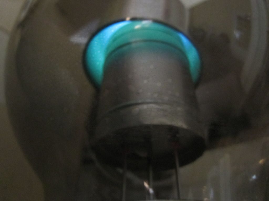
Unfortunately the plasma is shielded from the eye but inside you can clearly see the "show" a couple of these will provide perfect 600v to the gu81m.
This amplifier will be unique. A gem!
Unfortunately the plasma is shielded from the eye but inside you can clearly see the "show" a couple of these will provide perfect 600v to the gu81m.
This amplifier will be unique. A gem!

regardless of the colour here are all 470uf 450v caps in series (very good italian brands I tested in the past). Tested and resistor balanced..
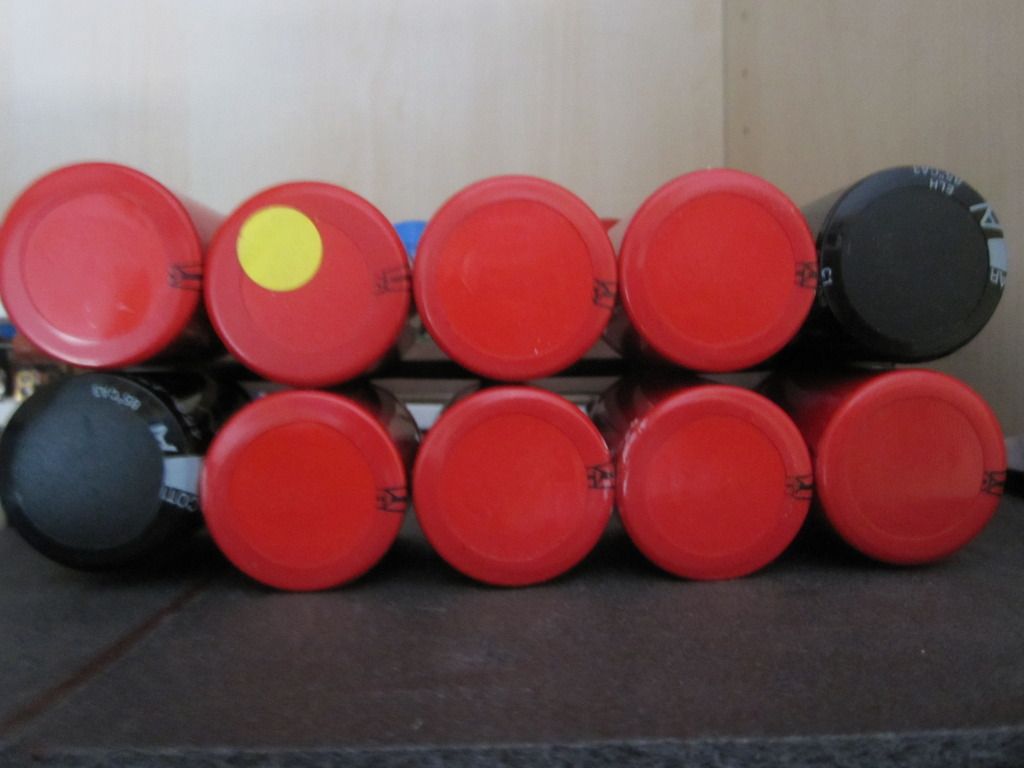
5 in series x2
should provide adequate filtering and protection against HV and surges..
even four of these could easily provide 1800v and with an additional 10% headroom almost 2000v. With 5 I get a total max rating of 2475v. Total capacity: 188uf. Should be plenty for the anode voltage.
There was really no other choice in terms of weight, space, cost ecc. I can afford to have one blow per bank so pretty safe against failure. In this amp I implemented the "every cap has a backup" rule....so every cap stage has a symmetrical (or in one case smaller) stage behind it. This way failure will not result in open circuits and nice 2000eur explosion. I'd really not want my bias to fail during operation.
Also I have a spare -150v line onboard to provide a backup if the situation should arise.
Hopefully I am not straying in the wrong direction.
🙂
- Status
- Not open for further replies.
- Home
- Amplifiers
- Tubes / Valves
- High voltage driver for AB2 operation GU81m tubes