deepanger said:
* whats that dissipation prob. with the low volts, and whats the
range of the volt "being low"?
Suppose you have 50V DC at the capacitors after rectification.
Now coinsider two loads, A and B.
A) needs 40V and draws 10A
B) needs 10V and draws 10A
Load A will dissipate 40*10 = 400W, while load B will only
dissipate 10*10 = 100W. However, in a linear regulator we have
a pass transistor in series with the load, and this transistor
must drop the difference between the 50V and the load voltage.
For load A, the transistor need only drop 50 - 40 = 10 V, so it
will dissipate a power of 10V*10A = 100W. However, for load
B it needs to drop 50 - 10 = 40V, so it must dissipate 40*10 =
400W. That is, the lower the output voltage, the higher the
voltage drop over the pass transistor. For the same current, it
will be hotter for smaller output currents.
Of course, there is only a problem if you have loads that draw
high currents at low voltages. Some PSUs have a foldback
protection so they are limited at a lower current for low
voltages.
OK, this one works,
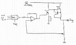
This design is modified from Horowitz and Hill and it works, it really works -- but you are going to have to add compensation. I found that the values in H&H and those which kept the device stable were different and no doubt you will the same. -- depends on the OPAMPs and the MOSFET's. <p>I use a 10 bit serial DAC from Maxim, since I have several laying around and have already written the code, but you can just tie the Inverting input of the opamp to +5 volt reference via a 10K resistor and adjust the voltage via the potentiometer (which is how it is described in H&H.)
Jack
Attachments
Christer said:
Suppose you have 50V DC at the capacitors after rectification.
Now coinsider two loads, A and B.
A) needs 40V and draws 10A
B) needs 10V and draws 10A
Load A will dissipate 40*10 = 400W, while load B will only
dissipate 10*10 = 100W. However, in a linear regulator we have
a pass transistor in series with the load, and this transistor
must drop the difference between the 50V and the load voltage.
For load A, the transistor need only drop 50 - 40 = 10 V, so it
will dissipate a power of 10V*10A = 100W. However, for load
B it needs to drop 50 - 10 = 40V, so it must dissipate 40*10 =
400W. That is, the lower the output voltage, the higher the
voltage drop over the pass transistor. For the same current, it
will be hotter for smaller output currents.
Of course, there is only a problem if you have loads that draw
high currents at low voltages. Some PSUs have a foldback
protection so they are limited at a lower current for low
voltages.
its obvious now,, and about the pass transistor its included inside any volt. regulator like the lm317 and others.. am i right?
well, after undestanding the dissipation prob. i dont think that
am going to face it since this ps. will specifically be used for
testing any upcoming amplifiers like the P3A and alike ones..
so i made it more easy now ithink,
i dont know yet any volt. regulator except that LT1038 but it only
can be regulated to 32V with 10A max. is this suitable for the P3A
and alike ones??
deepanger said:
its obvious now,, and about the pass transistor its included inside any volt. regulator like the lm317 and others.. am i right?
Yes
- Status
- Not open for further replies.
