A very popular DIY hybrid in Russia https://www.diyaudio.com/forums/solid-state/364747-zarathustra-hybrid-amp.html#post6456298

diamond buffer sounds much better
Uses a separate independent bias current source ("батарейка ").DIY hybrid in Russia
Last edited:
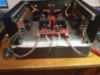
Waiting the final switching power supply modules the new test environment with both channles

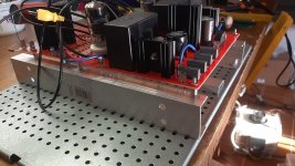
The switching power supply are arrived yesterday and I am happy of the result obtain, these are much better than Meanwell used in the first test.
You can't perceive difference in sound by hot switching between conventional power supply made of transformer, diode bridge, capacitors and these switching power supplies.
In some cases, as in my Solidstate Circlotron, this difference was noticeable but probably because this one doesn't use regulators that separate the audio circuit from the power supply.
After more listening sessions I can conclude that a good conventional power supply with transformers, schottly diode bridge and audio grade capacitors sounds a little better than the switching one.
In particular, even if the main characteristics remain unchanged, the sound is more relaxing.
I use only a DSC DSD source with HQPlayer so very near to analog source.
In particular, even if the main characteristics remain unchanged, the sound is more relaxing.
I use only a DSC DSD source with HQPlayer so very near to analog source.
Andrea, you may want to check LT4320 based mosfet bridge such as described in LT4320 based active rectifier for less switching noise.
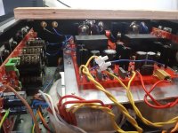
Those graphs do not show slew rate, they show risetime. The slew rate of those circuits is much higher.Here the new test environment to compare triplet darlington to diamond buffer.
I borrowed an already built module of triplet darlington from a friend of mine.
It is useless to measure the distortion because both have much lower values than the tube voltage amplifier.
I have used for both the same interstage capacitor Audyn-Cap Plus, this is worse than the Jantzen Superior Z-Cap.
Jan
Are you sure less noise with LT4320 ? Here a my simulation show more high frequency noise with the Ideal bridge.Andrea, you may want to check LT4320 based mosfet bridge such as described in LT4320 based active rectifier for less switching noise.
Attachments
No, but in most cases it is. I'd also recommend a snubber for best noise performance (see Simple, no-math transformer snubber using Quasimodo test-jig thread).Are you sure less noise with LT4320 ?
There are a few problems with LTSpice sim to estimate turn off switching noise (usually in 100s kHz to a few MHz range) which are:my simulation show more high frequency noise with the Ideal bridge
1. Most Diode models do not show turn off switching noise well enough.
2. Mosfet models show turn off switching noise better.
3. Simulation has to include parasitics such as leakage inductance, internal resistance and stray capacitance of transformers, ESL and ESL of smoothing capacitors etc.
I modified your sim by adding parasitics and using lower performance diodes but deficiency in diode model does not show any turn off behavior.
Bench measurement with scope is probably the easiest to see switching noise behavior,
Attachments
Are you sure less noise with LT4320 ? Here a my simulation show more high frequency noise with the Ideal bridge.
While LTSpice simulations are fun and a lot of help, simplified simulation is not close to real circuit behavior. @indra1 made good points. I would add some voltage source internal resistance, say 0.5 Ω. That would make voltage and current waveforms at C1 almost identical.
I measured around active rectifier circuits enough to confirm that their switching noise is an order of magnitude lower than with diodes and overall HF harmonics are lower, contrary to what first simplified simulation is showing.
As you put much consideration into component’s contribution to amplifier sound, you should check active rectification.
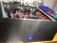
The final result in a 4", here has been used 2 custom toroidal transformers with secondaries for both stages (by Italtras.com)
Attachments

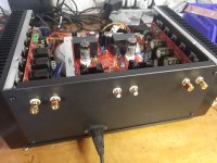
I will create soon the same amplifier in a 5" with standard transformers.
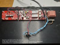
Here the last files to create the pcb, including the DC protection and softstart.
The pcb will be available on Ebay shop in the near future, I don't get money from this Ebay shop.
Here the last files to create the pcb, including the DC protection and softstart.
The pcb will be available on Ebay shop in the near future, I don't get money from this Ebay shop.
Attachments
-
7_Amplifier_End_driver_ver21b_ver22__2022-12-16.zip499.5 KB · Views: 199
-
Amplifier_End_driver_ver21a_2021-11-08.zip465.5 KB · Views: 180
-
Bridge1_2021-10-19.zip5.8 KB · Views: 143
-
IbridoneOutputARD100_new2022d_2022-11-14.zip173 KB · Views: 146
-
Prot_only_ver7_2022-12-28.zip45.6 KB · Views: 149
-
Soft_start_ver8_2022-12-28.zip46.3 KB · Views: 199
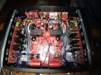
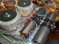
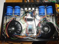
Here the version of a my friend with separated power supply using 2 x 42VAC 420VA toroidal transformers and 4 x 19000V 75VDC capacitors

Attachments

Pcb are available on Ebay shop but these are not cheap
https://www.ebay.com/itm/225455971488
I don't get money from this Ebay shop.
All files are available to produce these.
https://www.ebay.com/itm/225455971488
I don't get money from this Ebay shop.
All files are available to produce these.
- Home
- Amplifiers
- Solid State
- High Power Hybrid Amplifier