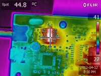
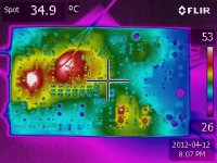
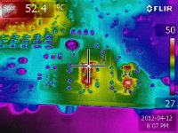
Thermal Map of DAC Board
Hopefully the images are self explanatory.
Input voltage to the board is 6.050V at 222mA.
I was surprised at the hex inverter.
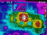
Hopefully the images are self explanatory.
Input voltage to the board is 6.050V at 222mA.
I was surprised at the hex inverter.
Attachments
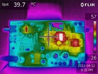
Hopefully the images are self explanatory.
Input voltage to the board is 6.050V at 222mA.
I was surprised at the hex inverter.
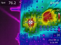
Your OPA2365 (76.2C) seems to be a bit hot... I'm been playing now for 30m and mine is just lukewarm.
I want one of those cameras....
Brgds
Last edited:
If you have the chance - compare this incarnation of WM8741 against the Audio-Widget ESS9023 from Qnktc or Yoyodyne. I have all three of them. I would like George to pull his act together and put the WM8741 on board in the framework of Audio-Widget. Just give us the three-wire control lines and no H/W control.
But then again, I haven't stripped it down or given it better power feed - but on the other hand I feed my audio-widget stuff from usb only... I haven't given it a chance really after mastering the filters to get the signal before the headphone circuit.
Brgds
But then again, I haven't stripped it down or given it better power feed - but on the other hand I feed my audio-widget stuff from usb only... I haven't given it a chance really after mastering the filters to get the signal before the headphone circuit.
Brgds
Last edited:
I have considered the Audio Widget, but wanted to get some experience first before I commit to the investment, and effort. I thought the boards were available unpopulated but don't seem to find a link. Shipped to me it is 190us for the complete 1.1 set.
Hopefully I'll have the 2707 tomorrow and can get that portion of the circuit working. Once I've got good signals through the 4192, I'll attach the Arduino and go that route.
Hopefully I'll have the 2707 tomorrow and can get that portion of the circuit working. Once I've got good signals through the 4192, I'll attach the Arduino and go that route.
Last edited:
I have considered the Audio Widget, but wanted to get some experience first before I commit to the investment, and effort. I thought the boards were available unpopulated but don't seem to find a link. Shipped to me it is 190us for the complete 1.1 set.
Hopefully I'll have the 2707 tomorrow and can get that portion of the circuit working. Once I've got good signals through the 4192, I'll attach the Arduino and go that route.
Yes, the 9023's seems to be discontinued (the tales of my strugling to get this one working... My first go on smd's in 20years+) but it works very nice even if there are additional straps of cabels repairing what I burned into pieces 🙂
Borge seems to have his incarnation - I might buy a few USB-I2S Modules and interface them myself to whatever I want in a modular way.
Investment is not so heavy... Soldering the MCU is outa this world though.
I have what I considered was a fine tip and premium 0.7mm 60/40 lead 🙂
Borges comes allready soldered - thanks for that.
Now as the not giving up easily guy that I am I bougth the YC-USB5102 kit with the same MCU. Now I have a finer tip and bought some 0.35mm lead melting at some 200+C instead of nearer 400. I will at maximum this time do at most 20 pins a day - I will slow the turbo down ;-)
But you should really check out why your OPA2365 is so freaking hot!
Brgds
Last edited:
Yes, it does look hot. It should only be dissipating 50mW.
You were right, Board Short that I missed on my initial inspection.
OP Amp is probably blown.
You were right, Board Short that I missed on my initial inspection.
OP Amp is probably blown.
Last edited:
Yes, it does look hot. It should only be dissipating 50mW.
You were right, Board Short that I missed on my initial inspection.
OP Amp is probably blown.
Good or bad (depending) to hear TheGimp! Soon we have the second board known of giving music!
Brgds
Left channel of the amp is dead. It looks like the op-amp as I see signals at the DAC output for both channels.
For some reason, when I pull the usb cable, the computer defaults to audio off and I have to right click the speaker in Windows Media Player and select "All Music". Then
Crazy Train! Ai, ai, ai.....
I just happen to have accidentally ordered two of the op amps so I'll change it tomorrow at work. No sense risking damaging the board if I can use the microscope and solder station.
I'm still concerned as the left channel output goes to +5V so I'm not sure I've found all the shorts.
That said, The DAC LIVES!
Both channels of the DAC are functioning as I can look at R+, R-, L+, and L- and see music on all four with the scope.
Weeeeeeeeeeeeeeeeeeeeeeeeeeeeeeeeeee!

I found a third short. Vout on the left channel is now at 2.24V instead of 5V so I think this might be it. I'll go out at lunchtime and pick up another USB cable (forgot to bring one) and see if it will play.
If so that only leaves the issue with S/PDIF. I don't think anyone has it working yet so it may be a design problem, or another short.
Current demand is now 162mA with no input signal.
If so that only leaves the issue with S/PDIF. I don't think anyone has it working yet so it may be a design problem, or another short.
Current demand is now 162mA with no input signal.
I haven't tested since I will probably never use it. I know my soundcard has s/pdif out. I probably have to screew the whole settings of the machine to get it working...
I'll think about it and hopefully someone else does it faster so that I don't have to ;-)
Brgds
I'll think about it and hopefully someone else does it faster so that I don't have to ;-)
Brgds
I'd like to use it with the S/PDIF out of my sound card to drive the DAC board. I'll then use it with AudioTester (audio spectrum analyzer, etc) to see if I get a better noise floor than with the on board audio card.
Are we the only two to get these boards working?
Are we the only two to get these boards working?
Go easy on my Turbon, I have a dozen sticks in the fire at the moment. The WM8741 is waiting for the audio-widget boys to define the protocol for talking to DACs with software configuration. If you are curious you can grab the current document archive for the USB8741 from this page.
FYI:
I no longer offer the USB9023 kit but do have 3 blank pcb it someone wants to populate them. The design uses a custom dual frequency Si532 clock with a .3ps jitter. You can buy them from Mouser (custom order) or from myself.
I still have 4 of the USB5102 kits left. This kit uses the PCM5102 DAC (no kidding) and the open-source UAC2 engine. Currently I use one with my Win7 netbook and the open-source ASIO driver for full 24bit/192k audio. sweeeet.
Happy listening,
George
Yoyodyne Consulting
If you have the chance - compare this incarnation of WM8741 against the Audio-Widget ESS9023 from Qnktc or Yoyodyne. I have all three of them. I would like George to pull his act together and put the WM8741 on board in the framework of Audio-Widget. Just give us the three-wire control lines and no H/W control.
But then again, I haven't stripped it down or given it better power feed - but on the other hand I feed my audio-widget stuff from usb only... I haven't given it a chance really after mastering the filters to get the signal before the headphone circuit.
Brgds
George, I have some years to catch-up after raising kids, my wifes dogs and the house and the melody goes on... So easy is not one of my tunes!
But it's good to hear that you are busy, it's healthy.
BTW - I have scrutinized this thingie and it uses 2-wire control so I rest in peace with the flock. But it would be nice to have sclk and sdin available for external tampering so one doesn't need to go thru the PC to change settings. Keep it in mind as a choice.
BTW George, could you make your boards half the size with only the MCU and needed stuff on them? I believe they would be outsold all the time... Of course with all the choices of what ditt and datt to use for whatever tweakings we would like. One rule though - it must comply with the audio-widget framework which shouldn't be a problem since the framework doesn't care of which dac one is using anyway...
Please?
BTW once again - you got an PM.
Brgds
Last edited:
There is busy and then there 12 hour days. 🙁
Yes, the USB8741 will use I2C to chat with the DAC. There are also 6 LDO regulators to handle all the fussy bits. Of course you can disable the regulators and use your own.
sigh.. every one wants a new toy for spring. OK, here is one and when I get the time I will make the boards for it. ( see .jpg) The board is 78mm X 60mm.
Totally untested but it has I2C and SPI control buses, MCLK can be manually selected to be 12/11Mhz or 22/24mhz. The Si532 has its own regulator. Again, the software to drive the I2C or SPI buses has not been written. If you are a programmer join the Audio-Widget google list and contribute.
The ADC I2S may not work as it is specific to the amateur radio SDR-Widget.
George,
Yoyodyne Consulting
QUOTE=Turbon;2983873]George, I have some years to catch-up after raising kids, my wifes dogs and the house and the melody goes on... So easy is not one of my tunes!
But it's good to hear that you are busy, it's healthy.
BTW - I have scrutinized this thingie and it uses 2-wire control so I rest in peace with the flock. But it would be nice to have sclk and sdin available for external tampering so one doesn't need to go thru the PC to change settings. Keep it in mind as a choice.
BTW George, could you make your boards half the size with only the MCU and needed stuff on them? I believe they would be outsold all the time... Of course with all the choices of what ditt and datt to use for whatever tweakings we would like. One rule though - it must comply with the audio-widget framework which shouldn't be a problem since the framework doesn't care of which dac one is using anyway...
Please?
BTW once again - you got an PM.
Brgds[/QUOTE]
Yes, the USB8741 will use I2C to chat with the DAC. There are also 6 LDO regulators to handle all the fussy bits. Of course you can disable the regulators and use your own.
sigh.. every one wants a new toy for spring. OK, here is one and when I get the time I will make the boards for it. ( see .jpg) The board is 78mm X 60mm.
An externally hosted image should be here but it was not working when we last tested it.
Totally untested but it has I2C and SPI control buses, MCLK can be manually selected to be 12/11Mhz or 22/24mhz. The Si532 has its own regulator. Again, the software to drive the I2C or SPI buses has not been written. If you are a programmer join the Audio-Widget google list and contribute.
The ADC I2S may not work as it is specific to the amateur radio SDR-Widget.
George,
Yoyodyne Consulting
QUOTE=Turbon;2983873]George, I have some years to catch-up after raising kids, my wifes dogs and the house and the melody goes on... So easy is not one of my tunes!
But it's good to hear that you are busy, it's healthy.
BTW - I have scrutinized this thingie and it uses 2-wire control so I rest in peace with the flock. But it would be nice to have sclk and sdin available for external tampering so one doesn't need to go thru the PC to change settings. Keep it in mind as a choice.
BTW George, could you make your boards half the size with only the MCU and needed stuff on them? I believe they would be outsold all the time... Of course with all the choices of what ditt and datt to use for whatever tweakings we would like. One rule though - it must comply with the audio-widget framework which shouldn't be a problem since the framework doesn't care of which dac one is using anyway...
Please?
BTW once again - you got an PM.
Brgds[/QUOTE]
Yeees, I want it. This is absolutely the right way to go. The drakes doesn't give a penny for nice dacs out there - they measure stuff in popularity due to connectivity to whatever...
Get this out and the choise is done for the Redmond giant.
Hint, get them populated...
Brgds
Get this out and the choise is done for the Redmond giant.
Hint, get them populated...
Brgds
Last edited:
standalone USB-I2S
I need to rework the board a little, move the clock ps and a few other fussy bits. It will be a while before it sees the light of day.
The real killer with my implementation of the open source UAC2 engine is the choice of clocks. The Si532 is not cheap from Mouser and slow to deliver and the processor add significantly to the final price.
Add in pcb, glue, fussy bits and shipping and it will cost close to $70. This design uses 0603 parts and will push your soldering skills. (I know it does mine).
George
Yoyodyne Consulting
Could you keep the clock as a module so it would be easily changed to whatever of choice? I agree that the Si532 is a very good starting point. But our mileage and taste varies...
Looking at your proposed board I find that there is more air to get out. It could be even more compact. But as you said it needs a little bit of rework.
But do not overdo it - the timing is now...
Brgds
Looking at your proposed board I find that there is more air to get out. It could be even more compact. But as you said it needs a little bit of rework.
But do not overdo it - the timing is now...
Brgds
Last edited:
Both channels are now up and running. Sound is crystal clear so I may not have damaged the output opamp (I'll probably change it eventually any way just to be safe).
I can handle 0603s (under a stereoscope), but please don't ever use 0402s or smaller (0201, 01005? Yikes I didn't know these pepper grains existed!).
That 144 pin tqfp on the other hand is a bear to work with by hand. Not so much soldering, as placing it in position and keeping it there until diagonal pins are soldered.
I like the fact that you keep your regulators close to the load and keep the inductance of the long traces at the input instead of output.
Last edited:
- Status
- Not open for further replies.
- Home
- Source & Line
- Digital Source
- High Performance WM8741 Upsampling DAC New Version build thread (show 'n tell too)