No. Q6 and Q7 will still see the difference between the rails and the signal. The problem is the low impedance due to C2/C3/R11/R12. A competent design would use a high impedance source (i.e. common emitter).
Ed
Ed
We can include the entire input stage, except for Q6 and Q8 - and then Tim won't see any ripple on the rails at all.
HBt.
HBt.
Q6 and Q8 are the ones seeing the ripple. They are differential amplifiers. The entire input stage including Q6 and Q8 must have constant rail voltages.
IMO, this amplifier is a fail. This board has many better designs.
Ed
IMO, this amplifier is a fail. This board has many better designs.
Ed
Among other things i would suggest to abandon the inverting phase idea, that s a very bad one because any inverting
amplifier that is connected directly to a source will sound awfull, and for that matter any configuration that invert the signal
phase between the source and the speakers, exemple is a non inverting amp with an inverting op amp inserted between
the source and the amp.
Now that i think about it that s surely the reason why designs that measure extremely well will be disapointing once tested with speakers.
Please don't rush into the component dimensioning, I just made a quick sketch and inserted N1 and N2, most of the resistors simply scaled - knowing that this is not correct.
So,
it would basically be no problem to operate the IPS (and even the VAS) with stabilized +/-18V.
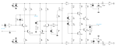
Regardless of whether there are better suggestions for low-power amplifiers in this forum or not, this is a 1980 design.
What can be done to improve this proposal slightly, or to make it work at all?
That does not solve the problem. Q6 and Q8 see the difference between their base and emitter voltages. That difference should not be affected by ripple.
N1 and N2 need to be in parallel with C10 and C11. Get rid of R20 and R21. This is a poor design even by 1980 standards.
Ed
N1 and N2 need to be in parallel with C10 and C11. Get rid of R20 and R21. This is a poor design even by 1980 standards.
Ed

"Tim - the extraordinary"
Suddenly I remember a very simple solution to Ed's problem /point of view. Two rectifier diodes and two proper charging capacitors isolate the IPS-VAS from the shared rails. No problem any more.
Suddenly I remember a very simple solution to Ed's problem /point of view. Two rectifier diodes and two proper charging capacitors isolate the IPS-VAS from the shared rails. No problem any more.
I'm beginning to feel sorry for the author of the article.This is a poor design even by 1980 standards.
Ed
Attachments
You nailed it. A waste of timeThis is a poor design even by 1980 standards.
Ed
To be honest, I have to admit that this insecurity also keeps me on my toes - so this time I'm just going to give the whole thing a try.Now that i think about it that s surely the reason why designs that measure extremely well will be disapointing once tested with speakers.
There is something you have left out, not said - please say it.You nailed it. A waste of time
😉
To be honest, I am just too lazy to elaborate on everything faulty with that design. Even in the eighties we knew better approaches.
I do not debate the "sound" of any power stages, but the circuit details from the view of good or bad analogue engineering.
There are many aspects to debate - too many.
I do not debate the "sound" of any power stages, but the circuit details from the view of good or bad analogue engineering.
There are many aspects to debate - too many.
To be honest, I am just too lazy to elaborate on everything faulty with that design. Even in the eighties we knew better approaches.
At this point I would like to emphasize that this circuit was not designed by me - and that it is precisely the many apparent inconsistencies that are the attraction of this project for me. At second glance, I still find the circuit clever and well thought out - but I would never adopt it 1 to 1, I emphasize “never”.
The obvious quirks or, to put it more kindly, peculiarities of the circuit can be ironed out - and the original idea of the circuit can be retained.
I am not interested in magically transforming a laboratory circuit into the ultimate, world's best circuit.
The more voices are heard shouting in unison how bad L.Stellema's circuit proposal is, the less they dissuade me from trying to win something from the circuit.
Even if I still find it very difficult to understand you, especially with the strange accumulations of " ;-)", you are addressing a crucial key point here. Namely the question of when you /we can call a design bad? Who or what decides this evaluation /rating?Then do debate the "sound" from the view of good or bad AUDIO engineering
The circuit obviously worked so well in the laboratory that it was decided to publish it under the title of high performance.
For my part, after the preliminary skirmish, I would like to know how this topology (type) plays in my home, on my loudspeakers.
Can you please fight this out in the “faith thread” - thank you, you already know which one I mean.Then do debate the "sound" from the view of good or bad AUDIO engineering
regards,
HBt.
"High performing" is at best a statement regarding some visual measurements, which, however, are irrelevant to audio.
"plays in my home, on my loudspeakers."
What is your home, your loudspeakers?
"plays in my home, on my loudspeakers."
What is your home, your loudspeakers?
Off to the next round. All previously criticized “errors” have been eliminated immediately. Whether the circuit will finally work with it (and thus) is another matter /story - from now on, let's talk about “Tim” and no longer about L. Stellema's “failure”.

"High performing" is at best a statement regarding some visual measurements, which, however, are irrelevant to audio.
"plays in my home, on my loudspeakers."
What is your home, your loudspeakers?
I created this thread especially for that sort of questions and answers!
You
- surely know by now that I'm an engineer, and as such I'm totally into measurements (i'm in love with measurements)
- can only score points with me at eye level, I would be happy to receive sensible, i.e. useful comments - you can leave the rest addressed to me, you will only bite on granite.
Apart from that, I can't answer your question about my loudspeakers satisfactorily, there are five pairs in my immediate living area alone.
It is helpful if you specify your question, but this thread is dedicated exclusively to “Tim”.
Perhaps we can agree that real measurements are a great thing /deal after all - but not relevant in the context of listening, of course.
kindly,
HBt.
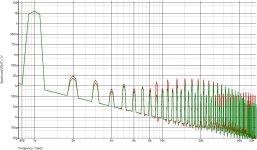
I will give some hope to fuel the debate, here what i got from two radical iterations of this weird design, but i ll warn
that it could be false hopes since even if those numbers look very good i m not really sure that it would be worth
the effort, for the time i ll just lurk by here and see where all this will end, although i have an idea of the final direction.
that it could be false hopes since even if those numbers look very good i m not really sure that it would be worth
the effort, for the time i ll just lurk by here and see where all this will end, although i have an idea of the final direction.
Attachments
agreed - disagreed.Perhaps we can agree that real measurements are a great thing /deal after all - but not relevant in the context of listening, of course.
kindly,
HBt.
Or do you think that there are no measured numbers at all that do correlate to listening experience?
- Home
- Amplifiers
- Solid State
- high performance 25W PowerAmp