Variac said:Carlos,
but now it's:
- Very small cap after the LM338 (I used 47nf poly), or no cap at all, if you use them very near the chips.
- From 4,700uf to 10,000uf total capacitance before the regs (I use 4,700uf on the MUR860's board and 2,200uf on the regulators' board).
- Small cap on the chip (I'd say between 22uf and 100uf).
Boy, it would sure help us who don't know much who want to hear your approach to have a clear schematic.
Variac, I'm sorry, I know what you mean.
I have a job that takes me all the day, and I usually don't have much time to do everything that I would like.
I'll try to make a schematic of the PSU one of these days, when time allows, and post it here.
Meanwhile, if you want, send me a PM and I'll help you.
Cheers
carlosfm said:
How funny...
I've ALWAYS used the insulated package.
Everybody (including you) advised me to use the uninsulated one, because it's better blah blah blah...
A I don't like to fiddle with insulators, spacers, etc, I always used the insulated package.
At the time, with the uninsulated package, you reported differences in sound with the insulator type, and you were fiddling with different types of heatsinks (copper, aluminium, etc) and reported listening tests.
I think you loose too much time making backward steps.
What's funny is that now it's YOU that recommend, and had the idea to use the insulated package.
For me this conversation is finished, I've said it all.
Have a nice day.
I don't see anything funny about that. If I learn that something is better, I just report it for others to try. If you knew insulated package sounded better, why didn't you make it obvious for others? I see, you were afraid they might copy you.
I believe you were only using insulated package because it's easier to implement. I'm using it because it sounds bettter. And I'm very specific about it now.
Even with insulated package there is still difference in sound when I'm fiddling with varuious types of heatsinks (copper, aluminium, etc) . I can only hope that you don't find that funny..
Peter Daniel said:I can only hope that you don't find that funny..
what is funny, peter, is that you take too much credit for things that others had the initiatives. the I-topology, insulated package, etc. are simply examples where you followed, but not led.
You are good at a lot of things, and everyone recognizes that. Equally, you aren't good at a lot of things too, and everyone knows that too. Not recognizing that and trying to claim where credit isn't due doesn't make you look good at all.
Variac said:Carlos,
So now you have my interest. I want to at least know
how "your" amp is made. the trouble is that it is like a puzzle to figure out what you have done.
From the other thread you sent us to at first, I am to assume you ares using Pedja's design for the regulated supply?
http://users.verat.net/~pedjarogic/audio/gainclone/supplies.htm
Then under Nuuk's advice, you made the caps 100uF?
but now it's:
- Very small cap after the LM338 (I used 47nf poly), or no cap at all, if you use them very near the chips.
- From 4,700uf to 10,000uf total capacitance before the regs (I use 4,700uf on the MUR860's board and 2,200uf on the regulators' board).
- Small cap on the chip (I'd say between 22uf and 100uf).
B]
In the power supply thread I tried a couple of time to summarize. After a couple of tries at some comments from Carlos I think it gets there. Here is the link.
http://www.diyaudio.com/forums/showthread.php?postid=414084#post414084
How to you guys make up the regulators?
Do you use a PCB, or do you hardwire the parts together?
Is a suitable (professional) LM338 regulator PCB available?
I am just about to start building my first GC, and I am considering going regulated provided I can make it look professionally done.
Do you use a PCB, or do you hardwire the parts together?
Is a suitable (professional) LM338 regulator PCB available?
I am just about to start building my first GC, and I am considering going regulated provided I can make it look professionally done.
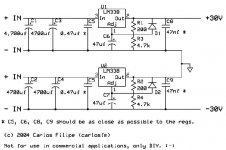
LM338 Regulated PSU schematic
I made this quick, no time to put the trafo and PSU diodes.
This PSU, with these component values, is what gave me the best results with the GC.
On the LM3886, LM3875, whatever, replace the 1000 or 1500uf PSU caps for something between 33 and 100uf.
Good luck!
😎
I made this quick, no time to put the trafo and PSU diodes.
This PSU, with these component values, is what gave me the best results with the GC.
On the LM3886, LM3875, whatever, replace the 1000 or 1500uf PSU caps for something between 33 and 100uf.
Good luck!
😎
Attachments
carlosfm said:Still those widely separated PSU caps?
Hi,
What is your explanation what is wrong with caps position on these boards?
Or someone else?
Thanks.
Regards
Milan
Re: LM338 Regulated PSU schematic
Carlos,
Thanks for creating and posting the schematic. It is very helpful in trying to follow your work.
I know you stated elsewhere that you consciously did not use a diode from pin 2 to 3 on the regulator as Predja does on his implementation. Did you think it was just not necessary or did you try it and think it affected the sound.
I will probably implement it for reliability reasons unless there is a truly noticeable sound difference. The GC I will implement it with will be going to a family member (building it with my son) and it will be physically out of my control at some point.
Thanks for communicating your implementation.
carlosfm said:I made this quick, no time to put the trafo and PSU diodes.
This PSU, with these component values, is what gave me the best results with the GC.
On the LM3886, LM3875, whatever, replace the 1000 or 1500uf PSU caps for something between 33 and 100uf.
Good luck!
😎
Carlos,
Thanks for creating and posting the schematic. It is very helpful in trying to follow your work.
I know you stated elsewhere that you consciously did not use a diode from pin 2 to 3 on the regulator as Predja does on his implementation. Did you think it was just not necessary or did you try it and think it affected the sound.
I will probably implement it for reliability reasons unless there is a truly noticeable sound difference. The GC I will implement it with will be going to a family member (building it with my son) and it will be physically out of my control at some point.
Thanks for communicating your implementation.
I built my LM338 circuits on small pieces of stripboard as shown in the picture.
I connected both channels to the transformer/rectifiers and got (the expected) 26.3 volts on all four outputs.
Then I put them aside and started building a case. Before I installed the regulator circuits, I changed the 220 uF's that I had on the output to 0.33 uF polypropylene.
I installed them in the case and connected everything up and on one of the circuits the 47 uF (35 volt rating) 'sizzled' after a few seconds so I removed the power PDQ!
I removed that board and checked for short circuits etc. Everything seemed OK so I soldered in another 47 uF/35v cap, powered up again and the same thing happened again.
I have triple checked the circuit and everything is OK. The other three circiuts work fine so what could be wrong with the faulty one(which is identical)?
I have checked the voltage into the circuits and it is correct voltage and polarity!
I didn't expect such a simple circuit to cause so much of a problem!
An externally hosted image should be here but it was not working when we last tested it.
I connected both channels to the transformer/rectifiers and got (the expected) 26.3 volts on all four outputs.
Then I put them aside and started building a case. Before I installed the regulator circuits, I changed the 220 uF's that I had on the output to 0.33 uF polypropylene.
I installed them in the case and connected everything up and on one of the circuits the 47 uF (35 volt rating) 'sizzled' after a few seconds so I removed the power PDQ!
I removed that board and checked for short circuits etc. Everything seemed OK so I soldered in another 47 uF/35v cap, powered up again and the same thing happened again.
I have triple checked the circuit and everything is OK. The other three circiuts work fine so what could be wrong with the faulty one(which is identical)?
I have checked the voltage into the circuits and it is correct voltage and polarity!
I didn't expect such a simple circuit to cause so much of a problem!
Did you take another transformer this time
so maybe C6,C7 (in Carlos schematic) with too low a voltage rating or bad batch of caps?
so maybe C6,C7 (in Carlos schematic) with too low a voltage rating or bad batch of caps?
After rereading your message I think you checked the obvious things that could happen.
Even a leaky diode would cause different output voltage so if that is corrrect...
I once had a problem with a switcher-PSU that didn´t like certain types of caps but a linear regulator shouldn´t give a damn unless it oscillates which it only does if capacitance before the regulator isn´t sufficient.
I think you should give some more info like in- out-differentials exact resistor values and so on.
Nuuk said:I built my LM338 circuits on small pieces of stripboard as shown in the picture.
An externally hosted image should be here but it was not working when we last tested it.
I connected both channels to the transformer/rectifiers and got (the expected) 26.3 volts on all four outputs.
Then I put them aside and started building a case. Before I installed the regulator circuits, I changed the 220 uF's that I had on the output to 0.33 uF polypropylene.
I installed them in the case and connected everything up and on one of the circuits the 47 uF (35 volt rating) 'sizzled' after a few seconds so I removed the power PDQ!
I removed that board and checked for short circuits etc. Everything seemed OK so I soldered in another 47 uF/35v cap, powered up again and the same thing happened again.
I have triple checked the circuit and everything is OK. The other three circiuts work fine so what could be wrong with the faulty one(which is identical)?
I have checked the voltage into the circuits and it is correct voltage and polarity!
I didn't expect such a simple circuit to cause so much of a problem!
Is this sizzling cap on the amp board? Could it be that that particular load point was drawing more current thn usual (dare I say, oscillations?), and/or there was something mechanically not quite fixed correctly? That would not show up on the voltage measurements.
Jan Didden
Sorry chaps, I was eating my evening meal when I posted last time so was little short on details! 😉
The circuit is more-or-less the same as that posted by Carlos (The Potuguese Man-of-War 😀 ) ) except for the resistor values which are 120R and 2K4 in my case to give the 26.3 volts output. I have 10000 uF ahead of the regulator circuits and 0.33 uF on the outputs. I also use both protection diodes.
I have measured the dodes and they all measure near enough the same.
The circuit worked fine when tested before and the only change was swapping the 220 uF's on the output for the 0.33 uF's.
I have re-soldered every joint and will re-test tomorrow morning as it is football time here! 😉
Maybe you got one of the fake capacitors that have been causing problems in Taiwanese computer motherboards for about two years.
They look real and work for a short while, but eventually they boil away their electrolyte and fail.
They look real and work for a short while, but eventually they boil away their electrolyte and fail.
Nuuk,
I know you are regulating from and to different voltages than Carlosfm but I am struck by the great difference in heatsink size.
Not related to your current issue but I was surprised to see how small the heatsink is on your power supply.
I know you are regulating from and to different voltages than Carlosfm but I am struck by the great difference in heatsink size.
Not related to your current issue but I was surprised to see how small the heatsink is on your power supply.
I know you are regulating from and to different voltages than Carlosfm but I am struck by the great difference in heatsink size.
Do you mean that mine are too small or too big?
Pedja reckons that mine will be fine.
Using LM338 in TO220 package (with any heatsink) to drive one or two 50W amps doesn't looks good to me. Any scope measurements with sine signal?
Regards
Milan
Regards
Milan
Nuuk said:Do you mean that mine are too small or too big?
Pedja reckons that mine will be fine.
If you have little voltage difference between input and output, say around 5 volts, that should cause no problems.
Anyway, if you ask me, I would use a bigger one.
I buy old CPU coolers at Cash Convertes for 0.5 Euros, and that's what I used here.
Good luck Nuuk, I dunno what may be your problem, strange...
Relax, check the circuit again after football, maby you'll find the problem.😀
Someone has asked me about the other protection diode, I don't use it because I think it is not need, but you may use it, extra protection makes no harm.
With a big cap on the Adj pin, like I use (47uf) the diode from Adf to Out is needed.
Without the other diode I can make a tighter layout, more important for me.
moamps said:What is your explanation what is wrong with caps position on these boards?
I can tell you on a PM, send me one and I'll explain you.
Here I'm just gonna say: that PCB is too bad, miserable layout.

Commercial spys are here, so...
I don't wanna give them clues on how to make a better layout, but I also don't wanna ruin their business.
- Status
- Not open for further replies.
- Home
- Amplifiers
- Chip Amps
- High-End Regulated Buffered Inverted GC