Migueeeeeeeeeeeeeeeeeeeeeeeel
How's your pre, did you finish it?
Come on Carlos, this is diy!!! Have you ever finish one of these things in your life?🙂
I use the same case for pre and GC, and with the changing of the transformer the whole thing is made into pieces.
Anyway, I have listened to it for a while and it is quite nice. But it looked so ugly that I changed some thinks to get it prettier (as its sound) andmade some other things: 100nF ceramic caps on the psu lines near the OPA627´s, without electrolytics. A 10uF electro and a 1uF tantalum in the buffer psu lines. Shorted some paths. Upgraded psu with 4700uF/100nF caps, regulator 7815/7915 and 1000uF/100nF ceramic caps. The 1000uF caps are a bit overkill but regulators are cheap in the case they fail. On the other hand, the pre is DC coupled to the GC and speakers are expensive

Now I was thinking if a low value resistor between the regulator and the output caps (something like 10R) could improve the performance of the psu...
Miguel
Miguel...
You killed the performance of a good op-amp with improper bypassing.
The OPA627 NEEDS capacitance NEAR it's PSU pins.
I'm talking about a 22~100uf electrolythic, bypassed with 0.1uf ceramic.
This is valid for every op-amp, but on the OPAs you can LISTEN to the disgrace if don't do it properly.
Do the same on the BUF634.
Oh, I said this and I repeat: I have no caps on the signal path (no input, no output) and I have 0.1mv DC one one channel, and 0.2mv DC on the other one.
Its sounds oh so good...🙂
Miguel, are you from Lisbon?
Hi Carlos,
I tried to follow the indications of the datasheets. But I have not listened to it yet. I will try like it is and adding then the caps. Do you think that 10uF for the buffers is low? The GC has an input impedance of 22k, so they are not working that hard... On the other hand, caps are cheap.
As for DC, I guess that if one rail fails, the output will go to the voltage of the other rail, which will be then amplified, goes through some high end cables and.......................
BTW, I am from Coimbra.
Miguel
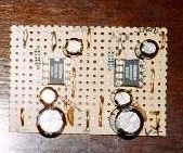
This is the buffer of the tape outs of my pre.
It has two OPA627s.
Look at the position of the caps near the op-amps.
They are where they are needed.
The ground passes through the op-amp, under the circuit and it's there where you need it too.😉
Due to the lack of space I didn't bypass with 0.1uf ceramics here.
The electrolythics are much more important here.
These are 100uf / 25v.
As I said, the OPAs love capacitance.
0.1uf ceramic alone is a disgrace.
BTW, I always bypass under the op-amp with 0.1uf from + to - pins.
Attachments
miguel2 said:
As for DC, I guess that if one rail fails, the output will go to the voltage of the other rail, which will be then amplified, goes through some high end cables and.......................
BTW, I am from Coimbra.
Miguel
DC stops at the input of my GC power amp, where I have a cap.😀
I would worry about one rail failing if I was running it from batteries.
BTW if you were from near Lisbon I would show you the animal playing.🙂
The fridge has some cool beer.😉
iCebReakEr409 said:How do you get so many damn expensive opa627 ?
I have a machine that spits them.

a machine that spits them

cool beer
perhaps i should reschedule my vacation......

carlosfm
Have you got a schematic for the power supply you are using in your preamp? I'm thinking of building a power supply for an active filter, and I'm thinking of building it around the 7818 / 7918 regulators. How much capacitance is needed?
Anyone else got schematics?
Have you got a schematic for the power supply you are using in your preamp? I'm thinking of building a power supply for an active filter, and I'm thinking of building it around the 7818 / 7918 regulators. How much capacitance is needed?
Anyone else got schematics?
Hi,
I also have a headphone amp with OPA627 and BUF634.
I agree with Carlo about having bypassing capacitance
near the opamps. I think it is important for all chips like
these to reduce oscillation.
I have a bit different opinion about 0.1uF ceramic caps.
They are actually, good especially when you want to avoid
oscillation at high frequency (RF level). Electrolytics will have
significantly high impedance at high frequency. On the other
hand, ceramics offer relative low level for wider range. It's a food
for thought when your amp has really big bandwidth (> ~MHz).
Then again, the new generation of electrolytics are awesome.
OSCON for instance has much better performance. ... (Don't
forget about burn-in period or recovery period)
Lookie mine. You can see cute little caps right close to PSU pins.
4.7uF 15V. Now don't comment about ugly chasis or use of glue.
... The thing can't take drills without shattering ... 🙁
(High Rez Po*n for Your Pleasure)
I cheated on PSU and used batteries ... do you have a heart to
forgive me?
Tomo
I also have a headphone amp with OPA627 and BUF634.
I agree with Carlo about having bypassing capacitance
near the opamps. I think it is important for all chips like
these to reduce oscillation.
I have a bit different opinion about 0.1uF ceramic caps.
They are actually, good especially when you want to avoid
oscillation at high frequency (RF level). Electrolytics will have
significantly high impedance at high frequency. On the other
hand, ceramics offer relative low level for wider range. It's a food
for thought when your amp has really big bandwidth (> ~MHz).
Then again, the new generation of electrolytics are awesome.
OSCON for instance has much better performance. ... (Don't
forget about burn-in period or recovery period)
Lookie mine. You can see cute little caps right close to PSU pins.
4.7uF 15V. Now don't comment about ugly chasis or use of glue.
... The thing can't take drills without shattering ... 🙁
An externally hosted image should be here but it was not working when we last tested it.
(High Rez Po*n for Your Pleasure)
I cheated on PSU and used batteries ... do you have a heart to
forgive me?
Tomo
My experiences
Ok,
Finally sorted out the pre-amp problems-see posts above, and I have one channel singing quite merrily withthe pre-amp attached.
Sound impact-SInce I have only modded one channel, I was able to compare with/without the pre.
Impressions:
Two words come to mind with the pre-Openess, resolution. The sound is so much more open, the normal gainclone sounding shut-in by comparison. Highs are better resolved, sounding less "hashy". Mids seem more forward, which I think is a function of the harder highs of the normal NIGC being tamed.
With the pre, the sound is louder (the pre has gain greater than 1, I am using 3.3k R in feedback and to ground and not 4.7k as recommended by carlosfm).
Overall, I would say that the sound is definately better-Thanks to Carlosfm and Pavel Macura for the idea.
A must build!
Ryan
😉
Ryan,
Thanks for your words.
After all, I'm not crazy, I'm not hearing things.😀
It's worth the trouble to build this pre.😉
You won't stop listening to music after it's done and singing.🙂
Tubed IGC.
Is it possible that the tubed IGC also improves on the stock IGC in the same way ? It would be interesting to see how this implementation ( OPA627 etc. with NIGC) compares with a tubed IGC. Anyone ?
Cheers,
Ashok.
Two words come to mind with the pre-Openess, resolution. The sound is so much more open, the normal gainclone sounding shut-in by comparison. Highs are better resolved, sounding less "hashy". Mids seem more forward, which I think is a function of the harder highs of the normal NIGC being tamed.
Is it possible that the tubed IGC also improves on the stock IGC in the same way ? It would be interesting to see how this implementation ( OPA627 etc. with NIGC) compares with a tubed IGC. Anyone ?
Cheers,
Ashok.
would be interesting to see how this implementation ( OPA627 etc. with NIGC) compares with a tubed IGC
Comparing a low voltage cathode follower against an opamp? Please pass me the aspirin. And the earplugs 🙂
A 6DJ8 IS a low voltage tube !
It is a +/- 35 volt tube stage against a +/- 15 volt opamp.
Both not doing quite the same thing considering the configuration.
Don't be dismissive .
Have a couple of bottles of beer while someone takes the trouble of trying it out. It WILL be interesting.
We have seen lots of No, No's working out well !
That's what DIY is all about in the first place .
Cheers.
Ashok.
Comparing a low voltage cathode follower against an opamp? Please pass me the aspirin. And the earplugs
Both very good if you ask me! 😉 (based on first-hand experience)
analog_sa said:
Comparing a low voltage cathode follower against an opamp? Please pass me the aspirin. And the earplugs 🙂
This is not just another op-amp pre.
- Status
- Not open for further replies.
- Home
- Amplifiers
- Chip Amps
- High-end preamp for my GC