matherp
Initially when I made the thread the idea was to have input and output buffers, but later when the group design effort failed after loosing many PCBs and so many parts and connectors (which were gifted to people participating in the group design) I decided to make the project on my own, I studied the data sheets with more care and came to the same conclusion that you have already mentioned that an input buffer should be used on PGA, whereas at the output stage PGA could drive 600 ohm load.
This was one of the reason, second reason was that I had already made a sound refiner based on OPA2134 and BUF634 which I intended to use between PGA and the power AMP.
Now when I have actually completed the code, tested the pre, I have come to the conclusion that it is better to keep a unity gain buffer at the input stage as it tends to isolate the PGA from the input and with OPA2134 the sound seems to get improved both at the lows and highs.
Another important conclusion is about the mute function of PGA.The datasheet says that the PGA goes into mute when pulled low and if pulled up unmutes. But if consideration is not given to it upon each power up and power down you will have a thump in the speakers, unless you are using TDA7294 as power amp. SO what I have done is now, pulled the mute pin low with a 10K resistor, and added a small line to the code so that upon power up the mute pin is low, after a pause of few millisecond the PIC corresponding pin for mute turns high, thus enabling the PGA chip, and at the power off, due to the 10k resistor the pin is pulled low faster so no thump.
Another important lesson learned was that make the project in blocks, not all of it the same time, it tends to make debugging the code easier, right now I have made a stereo version, but since PGA is a shift register it could easily be expanded to a modular version, and the same could easily be implemented to use QS5.1.
For the transformer if you see my design has separate power supplies, I even rewired my trafo for the same, but now I have experimented with it too, and this time used one toroid for both analog and digital supply.
Supply coming from the toroid is first converted to DC and then that DC was supplied to the digital section through a 10 Ohm resistor, but that didnt go well as LCD(VFD), PIC, PGA, Encoder tend to load the supply and the resistor was getting hot, therefore, I did put a diode in place of the resistor and its working alright. No hum, no noise. However, for the ground I still use the grounding technique recommended by T.I and that is digital and analog grounds are connected via one wire at one place.
So the answer to your question is yes. You can use on trafo for both digital and analog section.
For the code, my intention is to make comprehensive tutorial for people trying to make this type of project, so that they could customize it to their own needs, and thats where my entire code along subroutines will be shared.
My blog already has a good tutorial for another project for PS3.
Last edited:
Abid
Thanks for the helpful reply and the tip on the mute function. The picaxe pins (chip is a PIC 18F2520) power up as high impedance inputs so your solution will work fine for me.
Best regards
Peter
Thanks for the helpful reply and the tip on the mute function. The picaxe pins (chip is a PIC 18F2520) power up as high impedance inputs so your solution will work fine for me.
Best regards
Peter
completed boards
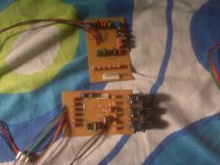
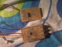
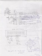
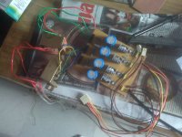
Hi please find find the phtographs of my completed boards.
It consists of Q surround board, PIC board with extra memory,IR & switch,6 channel volume control board,Power supply board.
I will be back with working source code & hex shortly.
No intention of becoming a teacher as Abid.
Hi please find find the phtographs of my completed boards.
It consists of Q surround board, PIC board with extra memory,IR & switch,6 channel volume control board,Power supply board.
I will be back with working source code & hex shortly.
No intention of becoming a teacher as Abid.
Attachments

- Status
- Not open for further replies.