Hi Guys:
After discussing with couple of friends we have decided to put our thoughts in the form of this thread which is intended To build a high End Pre with digipots 5.1 here are plans to buid the pre:
Inputs:
USB DAC using PCM290X
SPDIF DAC using CS8412/14+AD1865+Discrete parts
Digital Delay section:
QSound 5.1 Chip (a stereo to 5.1 channel coversion chip with build in digital delays)
Buffer:
OPA627/BUF 634 or
Star Buffer using OPA627 and discrete parts
Digipots:
PGA2310 x 3
Mute Realys
Digital Section
Build Around PIC16F877A and Choice of
Atmel AT89S8252
Both MCUs
Others
Buttons (menu, menu+, menu-, select,etc)
I.R
Rotary Emcoder (may be)
LCD 16x2 Out
Objectives:
Learning puposes only
Members so far:
Digi and Ferds have kindly consented to climb aboard this project, any other who wants join in this group deisgn effort is welcome.
Outline of the project will be posted sometime today. and then schematics of individual sections.
this is a very nice and interesting project.
cant wait to see the finish product
best regards
ferds
cant wait to see the finish product
best regards
ferds
Hi,
Sounds like a valuable project you are doing!
While you are upmarket from this SI project
you might find some pointers from it ! US$149
as a kit . How about offering balanced and
unbalanced options. That would assist DCX2496
users as well as 5:1 people. Why not plan it for
7:1 expansion so you ready for the future.
http://www.siliconchip.com.au/cms/A_30608/article.html
Regards and good luck!
AnthonyPT
Ad815
Consider using the AD815, it hugely outperforms the 627/634 combo!
More resolved highs, real air and extension,
Great mids, on par with 627
Deeper, tighter bass. real low end grunt.
Open and detailed soundstaging
Consider using the AD815, it hugely outperforms the 627/634 combo!
More resolved highs, real air and extension,
Great mids, on par with 627
Deeper, tighter bass. real low end grunt.
Open and detailed soundstaging
Now we are getting somewhere
Thanks guys for ur interest, sometime today or tomorrow me or hau will upload the project outline and schematics too, intent here is to learn from the experiences of others and help others do such a project themselves.
No doubt the project at silicon chip is very good but i m sure they wont give schematics, layouts and most of all firmware for the micrcontroller, which is intended to be posted here (may be)
Re: Ad815
That's right. 😀
Dr.H said:Consider using the AD815, it hugely outperforms the 627/634 combo!
More resolved highs, real air and extension,
Great mids, on par with 627
Deeper, tighter bass. real low end grunt.
Open and detailed soundstaging
That's right. 😀
So, can someone translate what this high end pre will be capable of?
Could I use it to replace the Receiver in my HT?
Michael
Could I use it to replace the Receiver in my HT?
Michael
Re: Ad815
thank you.
P.S.
I am planing a HDAM structure.
for mcu,It will be a couple of board design for 8051 or MAXIM.
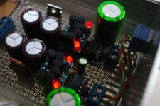
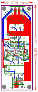
for the output buffer,I will try AD815.and I have a solid based buffer design,I have finished the archetype test lately.
photo attached
Dr.H said:Consider using the AD815, it hugely outperforms the 627/634 combo!
More resolved highs, real air and extension,
Great mids, on par with 627
Deeper, tighter bass. real low end grunt.
Open and detailed soundstaging
thank you.
P.S.
I am planing a HDAM structure.
for mcu,It will be a couple of board design for 8051 or MAXIM.
for the output buffer,I will try AD815.and I have a solid based buffer design,I have finished the archetype test lately.
photo attached
Attachments
huuuh,
how do you guys solder a chip with 0.65mm pinspacing? Evil, evil chip... 🙁
Anyway - i'm in, sounds like an interesting project!
Michael
how do you guys solder a chip with 0.65mm pinspacing? Evil, evil chip... 🙁
Anyway - i'm in, sounds like an interesting project!
Michael
digi01, do you think you need an additional buffer when using the ad815? It supplies a max of 500mA right from the chip.
slackman, there's a pretty helpful smd soldering tutorial here. Flood & suck works great for soic-alike pin spacings. I dont suck up the excess solder, i just use desoldering copper braided litze.
I've never felt the need to do it otherwise.
abidr, I think the usb dac portion is useless. I've built a few, all based on the ti PCM27/290x series but I haven't been able to bypass kmixer in windows. These dacs use standard windows usb audio drivers (wdm, usbaudio.sys). These drivers do not support direct kmixer bypassing so you'll have to do a driver yourself.
for more info check msdn .
Kernel streaming or asio-usb software stuff didn;t work for me either..
The kmixer algorithm is flawed in a number of ways. You'll never get bit-perfect output without bypassing it.
Can you actually hear the difference? yes, you can. Soundstaging is less accurate and the highs sound dull. This has no place in an otherwise high end pre like the one you are planning, imho.
I ended up buying a m-audio usb audiophile thing. Works great and comes with standard asio2 drivers
and SPDIF DAC
here are schematics of the SPDIF DAC, reciever section, along AD1865, analod section of the DAC consists of FETS. will be posted later.
Someone suggested the following changes in the reciever section:
- Use the inverter connected to pins 5 and 6
- Add series resistors in all data and clock lines
- Create space for bigger parts in the 8412 PLL filter network
- Reclock pin CS8412 pin 12 with pin 19
would anyone like to help in the schematics?
Attachments
Why not use WM8816 instead of PGA2310? it should outperform the PGA pretty easy I guess if you use OPA627/AD8610/20 or simular.
2c
2c
Tobias:
Ur suggestion about WM8816 is good, however, project already is at a stage where alternate pots could not be viable, though there may be other choices like wm8816, ssm2160, ds180x, secondly availability of these parts is also a problem.
Where do we go from here?
now guys we have to deicde where we go from here, we ll have to decide who will do what? so far i think ferds, digi and slacman are aboard the project, now we will have to decide who will do which section?
any ideas?
- Status
- Not open for further replies.
- Home
- Amplifiers
- Chip Amps
- High End Pre Group Design Invitation

