I'm sorry but I've been presupposed with trying to get reacquainted with some software. Is the LED green LED on the left or on the right in the photo with 2 LEDs?
I can not confirm a this moment, but for the voltage present in pin 2 I asume is on the right, but thinking about it, this condition make no sense to me, Because withh 12 volts in pin 3 of the hip4080 the green led will be on, this condition is contradictory, I will check and confirm
hi, i m working again in this amp i have the scope perri sugest me the owon digital
i remove all the output FETS, checked all good. good rdson good Vgth.
i removed the old HIP4080 installed a chp base and mounted in the base a new hip4080
at the beginning i got signal in pin 5 square about 10 volts 59 khz in pin 6 i have a saw tooth signal of 6.8 volts 59 khz.
signal l in pin 18 i got te same square signal. the same signal y got in pin 11 and 13
the hip 4080 got hot , and at this moment i have no square signal in pin 5 11, 13 and 18 (i have voltage but not oscillation) , the only oscillation signal i got at this moment is the saw tooth in pin 6.
i think the new hip4080 got damaged i do not know what is causing the excesive heat in the chip
the new voltages without the chip the second value is with the chip mounted in the base
1 12.89 | 11.99
2 13.14 | 12.8
3 12.7 | ~0.7 volts green led off after a minute 11.6 volts an green les on
4 0 | 0
5 0 | 6.32
6 6.52 | 6.4
7 6.65 | 6.63
8 0v | 4.02
9 0v | 4.02
10 12.9 | 12.3
11 0 | 9.9
12 6.6 | 9.9
13 0 | 0
14 0 | 0
15 13.5 | 12.78
16 13.15 | 12.78
17 0 | 0
18 0 | 0.6
19 6.65 | 9.54
20 7.6 | 9.6
i apreciate the help you kindly can give me
Attachments
Last edited:
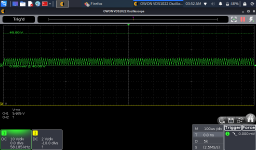
i let the chip to cool down turned on the amp and got signal again this are te signals in pin 11, 13 18 and 5 inthat order
Attachments
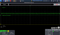
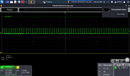
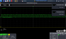
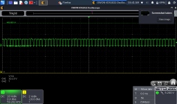
When setting the scope, set the timebase so you get about 3-4 full cycles.
For the vertical amplifier (with signals like this) set it to whatever gives you the most signal on the display without going off of the top of the display.
Is this scope a 1022 or a 1022I (I is important)?
Did you check the parts that I referred to in post 24?
For the vertical amplifier (with signals like this) set it to whatever gives you the most signal on the display without going off of the top of the display.
Is this scope a 1022 or a 1022I (I is important)?
Did you check the parts that I referred to in post 24?
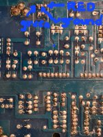
the resistors are ok two 1.4 ohm and two 10 ohm but the diode TVS1 give a diferent value than the TVS2 checked polarity inverted an give me not infinite. i have resistance value no matter the polarity i checked i desoldier it and checked good the value stays in the board, looking at two diodes aparently are like miror i mean is in the same circuit as tvs2, is normal i got difrent readings? ?? , i have 8.02 kohms in the board, with one pin of thr diode removed from the board.
ok i will congfigure the settings so the signal can be more detailed the scope is 1022 IWhen setting the scope, set the timebase so you get about 3-4 full cycles.
For the vertical amplifier (with signals like this) set it to whatever gives you the most signal on the display without going off of the top of the display.
Is this scope a 1022 or a 1022I (I is important)?
Did you check the parts that I referred to in post 24?
yes i checked the parts i answer in the post 27
Aren't the resistors supposed to be 1 ohm ±5%?
If the diodes are the same part number, they should read the same and like a diode if they're a uni-directional TVS.
The amp will work without the TVS diodes (for testing).
If the diodes are the same part number, they should read the same and like a diode if they're a uni-directional TVS.
The amp will work without the TVS diodes (for testing).
thank you Perry, i detected something weird , i unmounted the hip4080 from the slot and the resistance is gone i followed the paths and found a conection between pin 19 an pin 20 the resistance of 9.2 kohms was afecting betwen pin 19 and 20 i think can not be that value of R betwen 19 and 20, i think must be in megaohms.
maybe the hip8040 is defective or counterfeit.
thanks a lot maybe i have to stop with the repairing work until i get a new hip8040 from reliable supplier
maybe the hip8040 is defective or counterfeit.
thanks a lot maybe i have to stop with the repairing work until i get a new hip8040 from reliable supplier
I apologize, i have no time to continue working again with the repairs, resistors and hip4080 arrived i installed them, and now i have nice signal in all fets gates, installed fets and stay cool as ice with nice signal in all gates.
I connect in input rca a signal of 50 hz in i got nice and clean sin 50 hz wave in output.speakers terminal
But something weird is happenig with the indicador leds.
I Will post images and a video, because i suspecD the person who tried to repair the amp before, manipulated this leds and the starting process tells me that there is a posibility the leds are inverted.
Green instead of red, and red instead of green.
I apreciate your help telling me if this could be posible based in the video i póster
I connect 12v to remote and the amp begins with red, then two or three green flashes then turns and stays red but the amp is working.
I post voltages in hip4080 and ta4013 the Last IC controls the leds green and red pin 1 green and pin 2 red.
Hip4080
1. 41.5
2. 12.77
3. 0.265
4. 0.002
5. 6.62
6. 6.449
7. 6.311
8. 5.22
9. 5.223
10. 43.7
11. 37.6
12. 32.5
13. 5.761
14. 0.001
15. 12.79
16. 12.79
17. 0.01
18. 6.251
19. 29.97
20. 34.8
Ta4013
1. 12.78. to pnp transistor activates green
2. 0. to pnp transistor activates red THIS. PIN CONNECTS TO PIN 3 OF HIP4080
3. 12.78
4. 0.278
5. 12.72
6. 0
7. 0
8. 4.3
9. 4.14
10. 3.32
11. 12.79
12. 12.79
13. 12.79
14. 12.79
Thank you
Attachments
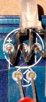
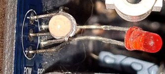
When the led turns red at the Last the relay engage, and i got output signal in sepakers terminal, thats the reason i suspect about the inverted colors of the leds, the led is a three pin the central pin is ground, so is esay if is ussoldered fron the board to invert it.
Another quesitos just in case if the inverted colors is not the problem, i Wonder if IC ta4013 could be replaced with cd4013?
Another quesitos just in case if the inverted colors is not the problem, i Wonder if IC ta4013 could be replaced with cd4013?
Last edited:
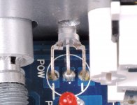
For what i see is not inverted. I post some pictures.
I do not know what else to test or check the red led stays on and green shuts of but the output signal at output is present and looks very good, for what i have seen in the board for the led stay in green pin 1 of 4013 must be low(this will activate the base of pnp that manages green ligth). And pin 2 must be high for the red led go off.
But im lost here because i saw a path between pin 2 of the 4013 and pin 3 of hip4080, if pin 2 of 4013 goes high that voltage reaches to pin 3 too,in the hip4080 this condition Will disable hip4080 i think.
Please corrct me if i'm wrong.
Attachments

Last edited:
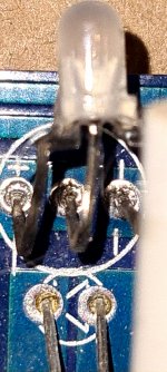
Thank you Perry the schematic helped me a lot.
The amp is working fine. The color was inverted.
I do not know if is a design problem or the tree pin led was replaced with another with pin configuración inverted.
But the circuit that triggered the green led is the same interconected to pin 3 of the hip4080, so if the hip4080 detected a problem the led light Will be green. If i left the led this way, will be confuse to see the amp working correctly with red ligtht, and when is tryng to start flashing in green.
Another think was not logical was:
how the amp can work ok, the pin 3 be low and the pin 2 of 4013 can be low too and the red led is on????
I inverted tree pin leds and now is logical the circuit design and operation and the led ligths.
The amp is working ok with clean and nice signal and the green ligth stays on. Like it should be (the soldier in the 3 pin led was not factory original)
Thank you again Perry
There is much more complicated to toubleshoot an amp tha has been previously repaired by other persons, you do not know what weird thinks can be done to the amps.
The board could have been laid out wrong for the LED or the LED may have had the reversed internal configuration, compared to the one that was supposed to be installed.
- Home
- General Interest
- Car Audio
- Hifonics BXI1606D