No I am just unsure what to do next. Why would i be getting so much voltage drop from pin 9/10 to the base of the drivers?
Either the load at the base is too great or the resistance it too high. The AQ20 shows a 510 ohm resistor. If that's the circuit you have, that's what I'd expect the reading to be.
Referencing AQ20 diagram R30 and R31 are at 220Ω. In my amplifier l i have they are 510 ohms. I assume adjusting that value would help?
R30/31 are pulldown resistors. They are not in series between pins 9/10 and the base of the drivers.
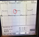
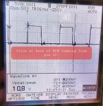
I adjusted r60 / r61 to 100ohms. Is the notch circled in red of any concern? I think this is the part of the waveform from the NPN pulling the signal up?
Taken from the irfp3206.
Taken from the irfp3206.
Attachments
Last edited:
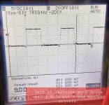
The LCD display makes it hard to see what that area really is. Adjust the timebase and vertical amplifier settings to make the red area fill the entire display.
That drive is still weak.
That drive is still weak.
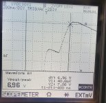
I think the glitch is where the FET switches on.
I think that the amp will not be reliable with such low drive amplitude.
Were the BD drivers purchased from a reputable distributor?
Bypass the R60 on both driver circuits. Do you have a better drive?
I think that the amp will not be reliable with such low drive amplitude.
Were the BD drivers purchased from a reputable distributor?
Bypass the R60 on both driver circuits. Do you have a better drive?
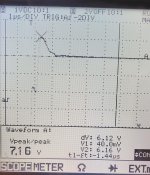
I just went in for the night but i did check the other side bank of irfp3206s and i have 3.4volts on the gate.
The initial side we started troubleshooting i am seeing 2.7volts.
I did get the BDs from Arrow electronics. Bd139-16 ON semi conductor. They were the older ones marked obsolete. I assume the ones they phased out because they were made with lead.
I will proceed tomorrow as instructed and lift the r60 and see how it goes.
Is the note on the left image what it's supposed to be? Were the drivers bypassed?
What was the B+ voltage when these were taken?
What was the B+ voltage when these were taken?
Drivers were not bypassed.
B+ voltage was 9.95V. I have 2ohm current limiter in series with B+.
All i did was insert a jumper in place of R60. Probe on gate. Ground lead from probe on source of the IRFP3206.
B+ voltage was 9.95V. I have 2ohm current limiter in series with B+.
All i did was insert a jumper in place of R60. Probe on gate. Ground lead from probe on source of the IRFP3206.
Why are you using a limiter? That adds a variable that makes it much harder to troubleshoot this via the internet.


Thank you Perry for all your help.
This should be ok with 0 ohm jumpers than? Package size of the resistors are 0805. Would they overheat outside of a failure?
This should be ok with 0 ohm jumpers than? Package size of the resistors are 0805. Would they overheat outside of a failure?
How much difference is there without the limiter and no bypass of the 510 ohm resistor?
Which resistors are you asking if they would overheat?
Which resistors are you asking if they would overheat?
In this amp R60 was originally 270Ω size 0805 surface mount. It is the resistor in series with pin 10 of TL494 and 2 sets of NPN/PNP drivers.
With 12.06V B+ there was an amplitude of 6.5v on the base of BD139.
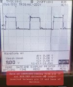
Now i have an amplitude of 11v on the base of BD139 with a 0Ω size 0805 surface mount in series with pin10 of TL494 and 2 sets of NPN/PNP drivers.
The reason I ask is the resistors were completely black when i replaced them most likely due to failure of the power supply and drivers but i wanted to make sure they weren't to small to begin with. I usually see these resistors in similar amps being 1/4watt through hole resistors.
With 12.06V B+ there was an amplitude of 6.5v on the base of BD139.
Now i have an amplitude of 11v on the base of BD139 with a 0Ω size 0805 surface mount in series with pin10 of TL494 and 2 sets of NPN/PNP drivers.
The reason I ask is the resistors were completely black when i replaced them most likely due to failure of the power supply and drivers but i wanted to make sure they weren't to small to begin with. I usually see these resistors in similar amps being 1/4watt through hole resistors.
Last edited:
- Home
- General Interest
- Car Audio
- Hifonics BRX 3016.1D waveforms