Addition of:
Augmented Feedback Error Correction (AFEC) V.2.0.
Can this system be used / added to the KX amplifier, with its standard / default / default values for resistors, capacitors?
Or would these values need to be specifically tailored/adapted for the KX, in order to ensure gain margin, phase margin and overall stability?
The kx-Amp is quite forgiving on transistor type so as long as you don't exceed Vce ratings and you make sure the hFE groups are the same for the symmetrical devices you are ok. What I mean by this is for example, if the PNP input devices are type 'B' suffix, avoid using type 'A' or 'C' for the NPN devices - they should all be from the same gain grade. The exception to this is on the VAS transistors where people have struggled to get the matching gain grades for the KSC3503 (2SC3503) and the KSA1381 (2SA1381) where I have indicated its ok to use different gain grades - this is what I have in my amp now and all the measurements you see are with these mismatched gain grades. The combined gain of the VAS stages with beta helper transistors swamps the minor differences in the VAS transistor for all practical purposes.
re AFEC. You really need to taylor AFEC for the amplifier and its not something I would recommend just adding on to an existing amplifier. If you look at my commercial site, there is an amplifier there (Model 1721) that uses AFEC. It took a lot of work to optimize it, and to make sure that it worked from unit to unit and works first time when I build it for a customer.
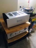
The kx-Amp distortion (measured) is already very good and the biggest issue - cross over distortion - is not there because its class A so my recommendation is that you just go with it as it is. I have only heard good feedback about it from those that have built it and BTW this is my amplifier I use every day:-
re AFEC. You really need to taylor AFEC for the amplifier and its not something I would recommend just adding on to an existing amplifier. If you look at my commercial site, there is an amplifier there (Model 1721) that uses AFEC. It took a lot of work to optimize it, and to make sure that it worked from unit to unit and works first time when I build it for a customer.
The kx-Amp distortion (measured) is already very good and the biggest issue - cross over distortion - is not there because its class A so my recommendation is that you just go with it as it is. I have only heard good feedback about it from those that have built it and BTW this is my amplifier I use every day:-
Attachments
Last edited:
Thank you for your valued advice and inputs.The kx-Amp is quite forgiving on transistor type so as long as you don't exceed Vce ratings and you make sure the hFE groups are the same for the symmetrical devices you are ok. What I mean by this is for example, if the PNP input devices are type 'B' suffix, avoid using type 'A' or 'C' for the NPN devices - they should all be from the same gain grade. The exception to this is on the VAS transistors where people have struggled to get the matching gain grades for the KSC3503 (2SC3503) and the KSA1381 (2SA1381) where I have indicated its ok to use different gain grades - this is what I have in my amp now and all the measurements you see are with these mismatched gain grades. The combined gain of the VAS stages with beta helper transistors swamps the minor differences in the VAS transistor for all practical purposes.
re AFEC. You really need to taylor AFEC for the amplifier and its not something I would recommend just adding on to an existing amplifier. If you look at my commercial site, there is an amplifier there (Model 1721) that uses AFEC. It took a lot of work to optimize it, and to make sure that it worked from unit to unit and works first time when I build it for a customer.
The kx-Amp distortion (measured) is already very good and the biggest issue - cross over distortion - is not there because its class A so my recommendation is that you just go with it as it is. I have only heard good feedback about it from those that have built it and BTW this is my amplifier I use every day:-
OK, so no AFEC, no funny business. You know, I am the type of guy that likes to ... test things, but if no apparent added value to be obtained, then not worth the risk.
I suppose that this time, I will make an exception to the naughty rule ...
and execute the project exactly as the designer envisioned it.
The design is simply too good from the looks, so I do not want to spoil it.
...
Audio-fila Nervosis needs hence to be kept at bay.
{While waiting for the PCB's delivery, funny/naughty things come to mind.}
"Audio-fila Nervosis needs hence to be kept at bay.
{While waiting for the PCB's delivery, funny/naughty things come to mind.} "
ha ha 😀
{While waiting for the PCB's delivery, funny/naughty things come to mind.} "
ha ha 😀
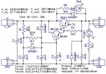
Ripple Eater - uses Darlington, loosing 2x Vbe on the way, but ensuring low output impedance.
How would a Complementary (Sziklai) version work out, for comparisons sake?
Probably, we would gain a slightly smaller dropout, 1 x Vbe + 1 x Vce_sat, but on the other hand, we loose on the output impedance. Something lost, something gained?
Overall, would a Sziklai-complementary version of the ripple eater be worth testing?
...
Additional question: I noticed that the KX PSU board does not have a ripple eater included. Would adding an off-board ripple eater provide any added benefit in the context of the KX amplifier? In the context of a). low listening levels (A), and b). high listening levels (AB)?
Last edited:
I have not tried the Sziklai in the Ripple eater so unfortunately cannot comment at this stage.
I am using a ripple eater with my kx-Amp. The current draw on a class A amp is high, so you get high ripple on the rails. The ripple eater reduced 1.5V ripple to about 14mV ripple pk-pk. There are some scope pictures in the link below
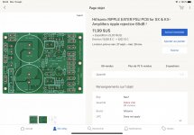
Simple Ripple Eater PSU for the sx and kx-Amplifiers
I am using a ripple eater with my kx-Amp. The current draw on a class A amp is high, so you get high ripple on the rails. The ripple eater reduced 1.5V ripple to about 14mV ripple pk-pk. There are some scope pictures in the link below
Simple Ripple Eater PSU for the sx and kx-Amplifiers
Another crazyman option is power MOSFET pass device with charge pumped, 1mA HV source for gate voltage. Now you can dial the (Vin - Vout) "dropout voltage" even lower than 2xVbe if you wish. It works on both polarities of supply, the neg supply with high threshold PMOS is no problem thanks to its charge pump.
Clock feedthrough noise reduction is left as an eminently solvable problem for the reader.
Clock feedthrough noise reduction is left as an eminently solvable problem for the reader.
I've seen mosfets used like this but never tried it. I think the bipolar route (conventional Darlington or Sziklai) is cheaper and altogether easier though.
Bonsai do you have a link to the heatsinks with the rounded fins as used in your kx amp build please. tia.
My pcb's arrived from Jim,s Audio yesterday and I have already obtained the transformer from Tiger Toroids. Just a few more parts to get although no one seems to have any 0f the 47,000uf 35V caps in stock at the moment.
My pcb's arrived from Jim,s Audio yesterday and I have already obtained the transformer from Tiger Toroids. Just a few more parts to get although no one seems to have any 0f the 47,000uf 35V caps in stock at the moment.
Last edited:
Can anyone tell me dimensions for one channel radiator to screw in every tran? I just finished hand saw cut on one block and I'm afraid that i miscalculated it. I have 11cm x 21cm. 2.5kg one.
Very tight fit. But should manage.Can anyone tell me dimensions for one channel radiator to screw in every tran? I just finished hand saw cut on one block and I'm afraid that i miscalculated it. I have 11cm x 21cm. 2.5kg one.
KX amplifier ... work is progressing.
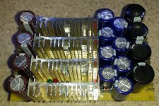
As Jim's set of PCB's does not actually include/provide for a capacitance multiplier,
I came up with a separate lab PCB, on which I will be implementing four channels of something like this.
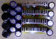
Actually powered up. Seems to work. Dummy Load was a set of resistors on heat sink, totaling 15 ohms.
Based on components found on the bottom of a drawer.
As Jim's set of PCB's does not actually include/provide for a capacitance multiplier,
I came up with a separate lab PCB, on which I will be implementing four channels of something like this.
Actually powered up. Seems to work. Dummy Load was a set of resistors on heat sink, totaling 15 ohms.
Based on components found on the bottom of a drawer.
Attachments
Well, yes, but the basic KX PCB set already has a PSU board, would be a pity not to use it, since included. That is the reason why a separate capacitance multiplier board. Four blocks, for PlusRight, PlusLeft, MinusRight, MinusLeft). Right and Left channels will have separate blocks.Have you checked eBay?
Fab
But there are those mega fat elko's on the preceding PSU board that comes as standard with the kit: 33000uF per rail. So these here are really just a fill in the blank, a bit of extra Capacitance on the input of the Capacitance Multiplier Board. Only because I had 3 spare cm of board from edge to the rest of the stuff thereon. The whole board is populated with elements of a height of 40mm, so as to achieve a compact form factor, that can be nicely fit into some limited space in a future enclosure / chassis.(C2 + C3) > C1
Yes, so it seems, perhaps, a bit uneconomical
Question: if intended for use in Bridge Mode, Would a pair of KX amplifier modules benefit in any way from a third transistor pair?
In Bridge Mode, a normal 8 ohm speaker would be "seen" by each half of the bridge as 4 ohms ...
So, asking the question differently - If I were to drive 4 ohm speakers by a single module, would there be any benefit from a third transistor pair?
In Bridge Mode, a normal 8 ohm speaker would be "seen" by each half of the bridge as 4 ohms ...
So, asking the question differently - If I were to drive 4 ohm speakers by a single module, would there be any benefit from a third transistor pair?
- Home
- Amplifiers
- Solid State
- Hifisonix kx-Amplifier