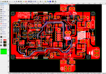
Hi Bonsai I made the changes on the PCB R9 33Ω now have it own GND trace to 0V right?
input transistors are closer from each other
R4,5 are now 1K
C13 and C8 have thicker traces
if you want I can post the gerbers later for one last check if need it 🙂
input transistors are closer from each other
R4,5 are now 1K
C13 and C8 have thicker traces
if you want I can post the gerbers later for one last check if need it 🙂
Attachments
OK, so I am now at the stage of stuffing everything into the chassis.
In essence the 'box' contains 2 ripple eaters (each fed from their own bridge rectifier) and 2 kX boards and Im now looking at the grounding scenario as detailed in the build guide.
The ground earth will be connected to the ripple Eaters via the 'ground Lift' earth connector.
In the guide the input and output connector '0V' connectors go to the xK amplifier boards along with the 'live' connections.
Following some threads on Amp earthing in some they recommend connecting the input and output (speaker return) '0V' connections to a star ground, and not the amplifier boards, to reduce current flow through the 0V tracks on the amp boards - and possible hum problems.
The current flows via the input connectors are probably going to be too small to have a measurable effect (?).
However, the amp output 0V line might well have an influence.
In this case would it be better to connect the '0V' speaker return to the Ripple Eater board and not the amp board ('Speaker Ret') itself? Say to one of the '0V' or 'Signal 0V' connectors on the RE's?
If this was done would it affect the functioning of the output Zobel Networks (which are also on the ripple Eaters)?
In short I'm looking at connecting the speaker return wires from the chassis connector to the individual Ripple Eater PCB '0V' lines rather than the 'Speaker Ret' on the kX board itself as a semi 'star ground' point.
Thoughts?
Hi Bonsai I made the changes on the PCB R9 33Ω now have it own GND trace to 0V right?
input transistors are closer from each other
R4,5 are now 1K
C13 and C8 have thicker traces
if you want I can post the gerbers later for one last check if need it 🙂
You've got it correct.
Only thing I would change is C13 - you still have the GND track going to the spkr return. Move the spkr return to the right and take the cap - track straight to the pwr GND. run the speaker return track then onto the pwr ground.
OK, so I am now at the stage of stuffing everything into the chassis.
In essence the 'box' contains 2 ripple eaters (each fed from their own bridge rectifier) and 2 kX boards and Im now looking at the grounding scenario as detailed in the build guide.
The ground earth will be connected to the ripple Eaters via the 'ground Lift' earth connector.
In the guide the input and output connector '0V' connectors go to the xK amplifier boards along with the 'live' connections.
Following some threads on Amp earthing in some they recommend connecting the input and output (speaker return) '0V' connections to a star ground, and not the amplifier boards, to reduce current flow through the 0V tracks on the amp boards - and possible hum problems.
The current flows via the input connectors are probably going to be too small to have a measurable effect (?).
However, the amp output 0V line might well have an influence.
In this case would it be better to connect the '0V' speaker return to the Ripple Eater board and not the amp board ('Speaker Ret') itself? Say to one of the '0V' or 'Signal 0V' connectors on the RE's?
If this was done would it affect the functioning of the output Zobel Networks (which are also on the ripple Eaters)?
In short I'm looking at connecting the speaker return wires from the chassis connector to the individual Ripple Eater PCB '0V' lines rather than the 'Speaker Ret' on the kX board itself as a semi 'star ground' point.
Thoughts?
Tony, what you are proposing is perfectly permissible and will not affect the Zobels. How to do this:-
Run the speaker return wire alongside the speaker output cable back to the amp module. Instead of connecting it to the amp module continue it along the amp module GND return back to the ripple eater board and terminate it there. Twist the spkr return wire around the cable it is being routed with.
This approach minimizes the loop area and therefore any radiated noise which will be at the signal frequency in this case.
+ and - to each amp module must be twisted with the GND return also.
Keep you input sockets next to each other. Make sure they do not connect with the chassis in any way. Join the signal grounds of the input sockets together. Run the two input cables together (twist or cable tie them, dropping the first one off at the first module and continuing to the other one around the edge of the chassis to the other module (pages 38-40 and 61-63 in the Ground Loop presentation - 'GLP' in my signature below ) . This keeps the total loop area of the ground returns between the channels to a minimum and therefore keeps hum to a minimum (the shortest route from the input sockets is not the quietest).
Once all assembles and tested, you can use the headphone trick (see pages 65 and 66 in the GLP) to finally dress your cables for minimum noise.
Remember also the transformer rotation trick - you can get very large noise reduction just by rotating it to find the radiated hum field null point (page 64 in the GLP)
Finally, there should only be 1 connection on the whole of the chassis to which the power safety earth and the 0V from the two power supplies connect. If you have more than one connection, you will get an earth loop.
On 90 dB sensitivity speakers with your ear up against the speaker cone, your amp should be silent with the inputs shorted.
Last edited:
You've got it correct.
Only thing I would change is C13 - you still have the GND track going to the spkr return. Move the spkr return to the right and take the cap - track straight to the pwr GND. run the speaker return track then onto the pwr ground.
ok I'll do that I'm back later thanks Bonsai 🙂
Tony,
NB - you must also twist the Zobel connection ('ZN' on the circuit) with the amp module ground to the ripple eater board.
IMPORTANT: DO NOT RUN THE AMP MODULES AT FULL POWER SINE WAVE WITH THE RIPPLE EATER
The ripple eater is designed to cater for music type signals - not full power sine of square wave testing. If you want to test at full power 8/4/2 ohms, link the series pass devices out on the ripple eater board while you do the test.
Tony,
NB - you must also twist the Zobel connection ('ZN' on the circuit) with the amp module ground to the ripple eater board.
IMPORTANT: DO NOT RUN THE AMP MODULES AT FULL POWER SINE WAVE WITH THE RIPPLE EATER
The ripple eater is designed to cater for music type signals - not full power sine of square wave testing. If you want to test at full power 8/4/2 ohms, link the series pass devices out on the ripple eater board while you do the test.
Thanks for the reply Bonsai
A little confused on the 'twisted wires'. There are 4 wires from the RE to the amp board, Power Pos, Power Neg, Amp Ground and ZN.
Should I twist all 4 together
or in 2 pairs:
a) Power Pos and Power Neg?
b) Amp ground and ZN?
Re: Running amp at full power sine wave using Ripple Eater:
Which would explain why I have blown a couple of the MJE transistors during my initial testing 🙂
Greetings to South Africa
You need twist together the +U, -U, ZN and GND wires...tightly...use cable ties to fix the twisted wires....twist the output cables SP+GND together...tightly and use cable ties here too...
You need twist together the +U, -U, ZN and GND wires...tightly...use cable ties to fix the twisted wires....twist the output cables SP+GND together...tightly and use cable ties here too...
Yes - this is what I mean Trelolelo
🙂
Tony - yes it would cause them to blow. Please see the Ripple Eater page on my website where this is discussed. (I have another high power version coming in a month or two)
🙂
Tony - yes it would cause them to blow. Please see the Ripple Eater page on my website where this is discussed. (I have another high power version coming in a month or two)
thanks Bonsai I was waiting for you awesome 🙂 I'm gonna check it a few more times before I order a few good day
Rallyfinnen,
Could you please upload LT Spice schematics to make it public? I mean the one that you posted under number 539 in this thread. It could save time for all those want to experiment.
BTW, I like the way you decreased the value of R44. My experience from other amp is showing it can suppress overal hum quite considerably 🙂
Ladislav
thimios did you check the updates on December 2020? I already check PDF page 4 🙂
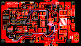
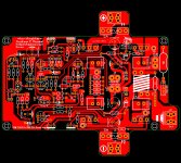
kx-amplifier: A very high performance 28 Watt class A Current Feedback Amplifier
kx-amplifier: A very high performance 28 Watt class A Current Feedback Amplifier
Attachments
I haven't built KX yet.
I have the SX.
May be it is time to salvage the enclosure and then i will go for KX😉
I will ask Bonsai😉
I have the SX.
May be it is time to salvage the enclosure and then i will go for KX😉
I will ask Bonsai😉
- Home
- Amplifiers
- Solid State
- Hifisonix kx-Amplifier