Bonsai you don't have the software Sprint Layout 6? ok ok, what I can do generate gerbers and use a gerber viewer software, give me a moment I'm gonna do that right now
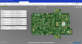
ok here is the gerber files also I made a 3D image if you want to check all sides
kx-amplifier Sprint Layout 6 file - Google Drive
ZofzPCB: FREE 3D Gerber Viewer + Premium STEP Export
gerber viewer online
Free Online Gerber Viewer | Circuit Board Rendering | GerbLook
kx-amplifier Sprint Layout 6 file - Google Drive
ZofzPCB: FREE 3D Gerber Viewer + Premium STEP Export
gerber viewer online
Free Online Gerber Viewer | Circuit Board Rendering | GerbLook
Attachments
How are you guys progressing with your amps? Has the fix solved the stability for everybody who tried it?
Hi Rally,
Following Bonsai's amendments to the original circuit in post #1 everything looks fine at this time.
Changing R4/R5 from 10K to 1K removed the parasitic oscillation I was getting and, together with the other recommended changes, has improved the square wave performance at 20KHz considerably. I've run one channel with and without the Zobel network without any detriment. As such I'll use the Zobel networks on the dual Ripple Eaters I have installed rather than trying to mount them on the amp PCB itself.
The only other changes I've otherwise made are:
1) Replaced input capacitor C4 from a 22uF bipolar to 2.2 uF polyprop (the largest polyprop I could get to fit - although the pin spacing of the polyprop is 5mm not 3.5 mm). According to simulation the low end 3dB point is around 7 Hz.
2) Using 24 Ohm as R25 such that the amp (AAB mode) will give around 42.5W output at 1V RMS input - to provide a little overhead before hitting the 50W max with 32.5V rails.
Otherwise, rearranging the PSU in the 4U chassis I'm using at the moment and afterwards will add the amp PCBs and do some actual tests on the "assembled product"
hi Bonsai did you check you messages? anyway here is the link of the Sprint Layout 6 file archive kx-amplifier Sprint Layout 6 file - Google Drive
let me know if you got the file 🙂
I add the SMD caps 1uF 50V to all electrolytic caps, also I add the 1K to the collectors of Q1 and Q2, about R4,R5 I don't remember if the values were changed 😕
oh I forgot the 10R and the 100uF 100V caps is on the board now 🙂
From my (limited) experience:
If running under class AAB on higher rail voltages (e.g. ± 35V) you will need to increase the rail capacitors (Original C6/C7 and C11/C12) to 50V so ensure your designed cap diameter is large enough to accomodate a larger cap can size (e.g. 12.5 mm - not 10 mm). On the original PCB the higher voltage 12.5 mm can size was a very tight fit.
This is mentioned on Anand's BOM.
C4, 22uF Bipolar has a lead spacing of 2.5 mm in the design but 5 mm seems easier to source - and allows one to substitute a polyester/polyprop (if low value - circa 2 uF) if required.
I had problems trying to get the 'right angle' fuse clips (MSR 504-HTC-210M
) as the 'straight' (PCB pins parallel to the fuse direction) clips seem more readily available but seems you have covered this already. Ended up using 'SMD' fuse clips.
Otherwise nothing else comes to mind with the original build although a purely 'rectangular' board might be beneficial without the 'wings' (Fuse/Line and the 'speaker out) connection(s)) extending beyond the basic rectangle.
polsol that can be changed of course I always try to give the PCB the best options possible example parts that can be accommodate better yes caps size fuse and other things the PCB that I'm doing is only for me to diy a similar design from the original is not to replace or to use of purpose of monetary gain "no way Jose!" is only for me to try out, if Bonsai check and is about fine or okay then I can tested and inform later in my time, like I said is not a replacement of the original design more like a modification update we can say I guess? 🙂
C4 on the PCB have already 5mm PD and 2.54mm
yes I see:
'straight'
'12.5 mm'
''right angle' fuse clips'
C4 on the PCB have already 5mm PD and 2.54mm
yes I see:
'straight'
'12.5 mm'
''right angle' fuse clips'
polsol that can be changed of course I always try to give the PCB the best options possible example parts that can be accommodate better yes caps size fuse and other things the PCB that I'm doing is only for me to diy a similar design from the original is not to replace or to use of purpose of monetary gain "no way Jose!" is only for me to try out, if Bonsai check and is about fine or okay then I can tested and inform later in my time, like I said is not a replacement of the original design more like a modification update we can say I guess? 🙂
C4 on the PCB have already 5mm PD and 2.54mm
yes I see:
'straight'
'12.5 mm'
''right angle' fuse clips'
I was not implying that you were going to commercialise Bonsai's design 🙂
Simply that there were some caveats as regards to the availability of some of the components, depending on the variant (Class/rail voltage) you build, and you check the availability of those recommended, in your country, before finalising the design.
Here in SA I can order from Mouser but there's a $60 delivery fee before an item is added to the shopping basket, then 14% VAT and import duties on top. 🙁
Hopefully components are more easily available in Puerto Rico.
vargasmongo3435:
Did you include the possibility for the cap on the bias circuit?
C17 here
https://www.diyaudio.com/forums/solid-state/329814-hifisonix-kx-amplifier-54.html#post6445971
I think that a square shaped board would be easier too. I like to clamp the outputs to the heat sink, and without the 'wings' a single bar and screw in between each pair of outputs could have been used.
For soldering the fuse holders, I just put a fuse in them to line them up before soldering.
Last edited:
I was not implying that you were going to commercialise Bonsai's design 🙂
Simply that there were some caveats as regards to the availability of some of the components, depending on the variant (Class/rail voltage) you build, and you check the availability of those recommended, in your country, before finalising the design.
Here in SA I can order from Mouser but there's a $60 delivery fee before an item is added to the shopping basket, then 14% VAT and import duties on top. 🙁
Hopefully components are more easily available in Puerto Rico.
wow $60 bucks? that hurt man 🙁 what is killing me is that in Puerto Rico there are not large electronic store they all banished and not many Puertorricans are interested in diy electronics also heat sink are not available locally I buy from Conrad or diyaudio store 🙂
Guys, my internet is down. Can only use iPad tethered to phone at the minute until probably Friday so answers will be delayed.
vargasmongo3435:
I think that a square shaped board would be easier too. I like to clamp the outputs to the heat sink, and without the 'wings' a single bar and screw in between each pair of outputs could have been used.
For soldering the fuse holders, I just put a fuse in them to line them up before soldering.
Providing better 'anchoring' of the output transistors is a good point that I hadn't thought of. I was more concerned about possible structural problems as 'fiberglass' does not have good shear strength and the 'wings' might be more subject to damage if too much force is applied (e.g. by pushing on or pulling off the 'fast-on' connectors).
I used the fuse inplace to solder on the SMD fuse holders. Works quite well but a little 'fiddly'.
ok here is the gerber files also I made a 3D image if you want to check all sides
kx-amplifier Sprint Layout 6 file - Google Drive
ZofzPCB: FREE 3D Gerber Viewer + Premium STEP Export
gerber viewer online
Free Online Gerber Viewer | Circuit Board Rendering | GerbLook
Hi vargasmongo
I took a look and here is my feedback
1.Try to move the 4 input transistor closer together - they should be almost touching. with good thermal coupling, DC offset drift will be minimized.
2.For the 33 Ohm HBR, I'd run a separate 0V track back to the speaker Return/Power ground connectors. Any mV ripple between it and the 0V will be injected into the input signal as it is now. Tun this track close to the existing 0V tracks to keep the loop areas small
3.Put top and bottom copper on the 1.8k feedback resistors to hep dissipate power - at full continuous power these dissipate 0.5W each - the copper will help remove heat
4.ALL connections to the Power ground must go to the power ground and NOT to the side where the speaker return is. The power ground is the star ground of the PCB. Even fractions of a milli-Ohm will degrade distortion performance.
5. The ground connection by the input side must be removed. If you use it, you will create common impedance coupling problems and possible ground loops
6. C13 and C8 connections must be made thicker
Otherwise, looks like a neat layout!
I will see if I can do those changes, thank you Bonsai
1. I might be able to do it sure
2. 33Ω I didn't understand what to do there "so it should be separate to GND?"
3. 1.8K feedback so copper top and bottom right? I'm not 100% sure here
4. is a bit confusing for me 😕
5. easy fix got it 🙂
6. C13 and C8 thick traces? ok ok
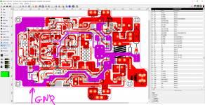
the traces for R9 33
here is the image of the top layout I remove the the GND connection
the pink highlighted traces is all GND star so it needs an additional separate GND?
is ok I'm gonna post after changes are done check and continue no problem thank Bonsai for checking the layout I'll keep posting as I go 🙂
1. I might be able to do it sure
2. 33Ω I didn't understand what to do there "so it should be separate to GND?"
3. 1.8K feedback so copper top and bottom right? I'm not 100% sure here
4. is a bit confusing for me 😕
5. easy fix got it 🙂
6. C13 and C8 thick traces? ok ok
the traces for R9 33
here is the image of the top layout I remove the the GND connection
the pink highlighted traces is all GND star so it needs an additional separate GND?
is ok I'm gonna post after changes are done check and continue no problem thank Bonsai for checking the layout I'll keep posting as I go 🙂
Attachments
Last edited:
2. Where the 33 Ohm HBR connects to ground - don't do it like this. You are mixing a power ground because you have large 1000uF decoupling capacitors on the power ground with 100/120 Hz decoupling currents flowing through the PCB trace resistance. This makes the heavy ground track a 'dirty ground'. Run a dedicated track from the 33 Ohm back to the power GND. Keep it close to the existing heavy ground. You only need a thin track -maybe 0.5-1mm
3. Yes - pour some copper top and bottom to help remove the heat from the resistors
4. You placed the spkr ret and power ground next to each other. Then you have 0V tracks returning that are joining on the spkr return and some on the power gnd return. Like this you are mix up high current and low current return tracks. Bring ALL the tracks to the power gnd side only. this creates a proper star gnd on the PCB.
Last edited:
Hi to everyone!I recently bought the PCBs as well as the new power supply PCBs and I am planning to use the amplifier to power 105 db sensitive horn speakers you think it will pair nice? will the noise floor be too high? should I go forward and buy the parts or look at other designs?
That’s exceedingly high sensitivity. You must use the ripple eater board with it.
To be honest, with that sensitivity speaker you really only need about 5-8 watts.
To be honest, with that sensitivity speaker you really only need about 5-8 watts.
- Home
- Amplifiers
- Solid State
- Hifisonix kx-Amplifier