Hello, I want to build an amplifier based on a op-amp, with at least 10w rms power with low distortion.
And i found this https://www.by-rutgers.nl/SSA-30W.html
I will use cheaper op-amp, maybe 5534?
Which one of the schematic to build? I think I will use only "overall feedback" without the jumper shown in the schematic, I would like to keep it simple as possible as well.
Also what is the use of bootstrap? ( used for more power output?)
Do I really need it? Can I just build the first schematic without C44 and 220pf from op amp to ground for stability like it says. I will make my own PCB.
May I use 15 zener for the op-amp? My power supply is only 2x 20 V dc ( Also i thought about using a pc power supply board + the power supply from a car amp that I have laying around +-22v, so I can fit them in a small enclosure)
Im curious what you think about this amp and if it's worth building.
Cheers, Bruno.
Bruno, have you given up hope of your Elektor amp? 😉
Such designs usually are OK. But if you want to build something nice, try to find something that has been built by many and is regarded well sounding. Meany designs measures well but doesn't really please our ears.
Why not build my "Baby Godzilla"? You may be the first person in the world except me. My friend Mia thought it sounded better than my class A amps.
The diagram isn't available, but I can send it to you.
Cheers
Please send it, No I don't but I'm trying to figure out what is wrong.. I want to build another " high quality " amp for my tv..
Also I saw Apex AX6 got very positive feedback from people
Also I saw Apex AX6 got very positive feedback from people
If you're looking for good sound quality pay attention to the opamp supply impedance. With just a couple of mA output current, 3 terminal regs have surprisingly high Zout. You're likely to get more satisfying sound using shunts.
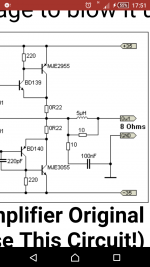
Can you please tell me in this schematic with opamp, can I ommit the 1 ohm resistors? What are they for?
Are they for temperature comp, in the schematic it says the are for power limit.
i have to buy pcb, than Im gonna make the apex 😀, but till than i still have one 12x8 cm and i will build this for fun and see how it sounds,
Are they for temperature comp, in the schematic it says the are for power limit.
i have to buy pcb, than Im gonna make the apex 😀, but till than i still have one 12x8 cm and i will build this for fun and see how it sounds,
First of all Bruno, try to spark up your Elektor amp!
You mention that the same dist occurs with two amplifiers. This suggests that something else is wrong. Just take it easy and sort things out and everything will be just fine.
I remember that old Elektor amp. For several months I couldn't get it to work. I tried everything. But I didn't try to connect the emitter and collector of a transistor the right way, despite that "EBC" was marked on the device.
The reason was that I had a crappy transistor tester that insisted that the emitter was the collector and vice versa. I trusted that crappy tester more than the printed "EBC" that was marked on the actual device. Sometimes you get stuck in your head.
I need to measure every component on that elektor amp, because I changed( in LTSpice this removed distortion/ oscillation) the 100k" gain" resistor to 200k and I dont know why, as soon as I applied power, DC went to the output so something is fryed..And someone want me to build a 15w Amp at least, so I started building this op amp based Amplifier.. Can you please tell me if it's ok if i leftbout the 1 ohm resistors, I think the should be from collector to output on both transistors, for temperature compensation, or am I wrong? Usually emitters are with 0.2-0.5 ohm resistors to output, but this design is different, On Rod Elliott's design emitter of BD's go to collector of power transistors and than with 0.5ohm to "output".
Attachments
You will be fine with Your +-20V DC supply. There is no voltage gain in the output stage (100% local feedback). The available voltage swing is limited to what the op-amp can deliver. If You decide to run the op-amp from +-15V rather than +- 18 the available output power will be reduced.
The 1 ohm resistors are for over current protection and for balancing the current between the output transistors if You decide to use parallel.
The article mentions oscillations. These are to be expected since there is no local feedback around the op-amp. These are often cured by connecting a small capacitor (40 pF or so) from the output of the op-amp to the -input.
Thank you, I put the feedback from output of transistors to inverting input not from output of the OP amp, can i use 15v zeners for the OP amp only? (i dont have 7818) how to calculate the zener series resistor for 20v can you help?
Last edited:
If you want to build a really cool amp, that could sound better brand of amplifiers, you can build it for this schematics. This is a very simple amplifier, but there aren't many amps better than him.I want to build an amplifier based on a op-amp, with at least 10w rms power with low distortion.
An externally hosted image should be here but it was not working when we last tested it.
Due to the deep NFB
An externally hosted image should be here but it was not working when we last tested it.
http://s1.stuffed.ru/y2017/01-04/0/468022.png
An externally hosted image should be here but it was not working when we last tested it.
amplifier has high fidelity sound.
An externally hosted image should be here but it was not working when we last tested it.
http://s1.stuffed.ru/y2017/01-04/0/468024.png
Anyway, you have to try.
Attachments
Last edited:
It's easy. We have a
great voltage,
small voltage (Zener)
and 2 current:
1. which consumes opamp (5...10 mA)
and
2. need for Zener (5 mA or more).
You subtracted from a value large voltage (V) value small voltage (V) and divide by the total current (mA).
So you get a resistor value in the kilo Ohm.
great voltage,
small voltage (Zener)
and 2 current:
1. which consumes opamp (5...10 mA)
and
2. need for Zener (5 mA or more).
You subtracted from a value large voltage (V) value small voltage (V) and divide by the total current (mA).
So you get a resistor value in the kilo Ohm.
Last edited:
So, 20v - 15v: 20 = 0.25 kilo ohm, 250ohm resistor
This resistor is in series with zener or in parallel
Can you draw in paint please?
And thanks for answering
This resistor is in series with zener or in parallel
Can you draw in paint please?
And thanks for answering
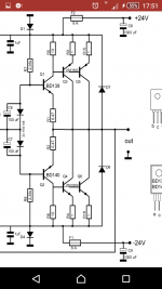
T117: Russians seems to love complicated amplifiers! All circuits you have shown are some sort of anti-Nelson stuff.
First an OPamp with a lot of transistors, then a emitterfollower followed by a cascode, followed by a folded cascode and then a triple buffered output stage. Phew....
And no local NFB around the OPamp.
First an OPamp with a lot of transistors, then a emitterfollower followed by a cascode, followed by a folded cascode and then a triple buffered output stage. Phew....
And no local NFB around the OPamp.
What is the use of the diodes on the rails? And the others, they are not specified what type theyvare as well? The ones from output to rails are for voltage not going back? Can i omit them like in first schematic or They are of use?
Hi!T117: Russians seems to love complicated amplifiers!
You're absolutely right. You don't get me wrong: the russians don't like complicated amps, russian like the best amps. You know: Cadillac, Volvo or Mercedes is a good car, they can't be simple cars.
I have to admit, that the circuitry of the Pass, makes me cry. 🙂All circuits you have shown are some sort of anti-Nelson stuff.
1. The triple output stage is always needed, regardless of the type of VAS. This output stage has a high linearity. I do not offer a simple and bad decisions.First an OPamp with a lot of transistors, then a emitterfollower followed by a cascode, followed by a folded cascode and then a triple buffered output stage.
2. VAS contains 4 of the transistor. This is a very small number and this is the best solution how to get out of this small number of transistors is such good value of THD.
Yes, the local loop NFB is not here. It's not necessary. Local loop NFB reduces the depth of the NFB of global loop and increases distortion. For example, opamp has a gain of 25,000 times. If you cover opamp a local NFB loop, the gain of the cascade will fall to 10 times. Loss of depth NFB equal to the quotient from dividing the 25,000 / 10 = 2,500. Distortion will increase.And no local NFB around the OPamp.
The amplifier is not so complicated and incomprehensible that it was impossible to build. But what you get will surprise you and be better than any more complex and expensive amplifier.
Last edited:
So, 20v - 15v: 20 = 0.25 kilo ohm, 250ohm resistor
This resistor is in series with zener or in parallel
Can you draw in paint please?
And thanks for answering
An externally hosted image should be here but it was not working when we last tested it.
http://s1.stuffed.ru/y2017/01-05/0/468386.gif
- Status
- Not open for further replies.
- Home
- Amplifiers
- Solid State
- Hi-Fi OP-AMP based Amplifier?!