N stands for Negative. Negative feedback.
T117. This is interesting. You are the first anti-minimalistic person I ever have had the chance to discuss amplifiers with!
For me it's simple( 😉 ). Simple circuits makes simple distortion ( even though the level is somewhat higher ) and our brains are glad, they doesn't have to try to analyze those tiny complex patterns that are generated by some high NFB complex stuff.
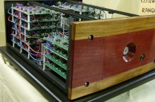
What do you think of my "Godzilla" amp that I posted here some time ago? It has a NFB of around 60db up to at least 300khz. But of course, that's absurd, a real amp must be domesticated in th HF, but the thing seems to be stable, and that is primarily due to it's simplicity.
T117. This is interesting. You are the first anti-minimalistic person I ever have had the chance to discuss amplifiers with!
For me it's simple( 😉 ). Simple circuits makes simple distortion ( even though the level is somewhat higher ) and our brains are glad, they doesn't have to try to analyze those tiny complex patterns that are generated by some high NFB complex stuff.
What do you think of my "Godzilla" amp that I posted here some time ago? It has a NFB of around 60db up to at least 300khz. But of course, that's absurd, a real amp must be domesticated in th HF, but the thing seems to be stable, and that is primarily due to it's simplicity.
Bruno, you seems to be young and enthusiastic. 🙂
Perhaps you should concentrate on one thing at a time. But when it comes to PCB making, I posted a "diy howto" some time ago. Maybe this can help?
http://www.diyaudio.com/forums/construction-tips/280597-ultimate-diy-pcb-guide.html
Perhaps you should concentrate on one thing at a time. But when it comes to PCB making, I posted a "diy howto" some time ago. Maybe this can help?
http://www.diyaudio.com/forums/construction-tips/280597-ultimate-diy-pcb-guide.html
Yes Im 20 😀, I saw usually people print the pcb ( actually pcb means printer circuit board...) than put the paper on the board heats it, than wraps the paper in water so the black ink remains on the board..
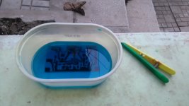
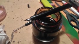
My printer died...so I do it with " tar, pitch..I dont know how is it called in english,) and a pen like this one
My printer died...so I do it with " tar, pitch..I dont know how is it called in english,) and a pen like this one
Attachments
I was also 20 when I built my first amp, the one that oscillated. I remember I was impatient and enthusiastic and made a lot of mistakes. Now it's your turn to do all those mistakes. 😀
in english, just say "permanent ink magic marker" 🙂
wow, that brings back memories Bruno. I am LONG past 20 🙂 back then, i did it with very solidly black ink magic markers. i found at the time that a statedler lumocolor no. 317 black marker was far and above the best marker for making fabulous quality patterns for pcbs and i never had to retrace. i see they still make them and they are even refillable! i wonder if the ink is still the same ....
mlloyd1
mlloyd1
Happened across this post.
What is your aim? To build something from scratch? Or to build a simple amp? or??
Seems to me the "chipamp" approach is simplest and most free from potential errors.
The Pass design F5 (or a similar amp of his) have fewer parts and sound very good.
Boosting the current out of an opamp front end has been done many times, I seem to recall a neat schematic in one of the opamp app notes from the "last century" probably National Semi that used the opamp driving a load resistor and sensed (directly with a transistor) the current drawn via each rail to drive an output stage.
Then too, when I saw the title I thought of what Blue Circle (Canada) did for an "opamp amp"! Maybe you want to try this instead?? 😀
Attachments
Also. In this post, q3 and q4 dont need ressisotrs from collector to output ( 0.2-0.5 ohm/5w? For temperature compensation or what is called
Hi!What do you think of my "Godzilla" amp that I posted here some time ago? It has a NFB of around 60db up to at least 300khz. But of course, that's absurd, a real amp must be domesticated in th HF, but the thing seems to be stable, and that is primarily due to it's simplicity.
Please give a link to this topic.
Nothing to worry about. I also did that once.Yes Im 20 😀, I saw usually people print the pcb ( actually pcb means printer circuit board...) than put the paper on the board heats it, than wraps the paper in water so the black ink remains on the board..
My printer died...so I do it with " tar, pitch..I dont know how is it called in english,) and a pen like this one
Addition. The deeper NFB, the better the sound.Thank you, Also what is nfb? Fb stands for Feedback and N?
Member
Joined 2009
Paid Member
T117. This is interesting. You are the first anti-minimalistic person I ever have had the chance to discuss amplifiers with!
I'm another person who has discovered the benefits of deep NFB and a few more transistors. My TGM8 amplifier sounds much better than my simple ones.
http://www.diyaudio.com/forums/solid-state/245619-tgm8-amplifier-based-rod-elliot-p3a.html
That TGM8 isn't that complex. In par with the old AKSA amp? It is regarded well sounding.
Perhaps the sugjectivist amps and the more THD focused amps tend to have different virtues? A short, moderate NFB may give the amp a sound that lets you absorb the music and sink deeper into the sofa. A bit introvert.
The THD optimized ones perhaps gives you a more stringent feeling - the one that makes you sit right up in the sofa an exclamate: "This is seriously good stuff".
OK: T117: my Godzilla site.
http://www.diyaudio.com/forums/solid-state/300687-godzilla-class-ab-amplifier.html
But that one is more of an extreme concept amplifier. The one I'm currently listening to is a baby version - more domesticated and suited for real life.
I call it Baby Godzilla.
But perhaps we are off topic now. Excuse us Bruno, but it's so fun to let the associations wander away
One channel is done BUT, the 6 ohm resistors on output can be better replaced by 10 ohm or 2in parallel 5ohm? ( i dont have 6ohm..) Also BD139 and 140 have 0.47 ohm resistors on emitters, But small wattage not (5w) would be ok 1 ohm? I dont have space for big 5w 0.47ohm ( and i dont have 0.47 - 0.5 ohm small res)ALSO IN THE SCHEMATIC THERE ARE SMALL POWER RESISTORS there...sorry for caps lock.
The Rutgers.nl/ssa-30W diagram doesn't have any 6 ohm resistor.
The emitter resistors on the BD139/140, to make 0.47 ohms you can parallel two 1 ohm resistor by stacking the second on top of the first. You can bend the leads of the second around the first resistor.
There is not a wattage listed on that diagram. If you have 5 watt resistors and want to save board space, you can put a long resistor vertically with one lead short and one lead long. The one ohm resistors on emitter of the output 2SC5200/2SA1943 might draw 1.5 amp on 4 ohm speakers, so yes, at maximum power 5 watt resistors would be appropriate. If you have a lot of 1 ohm 1 watt resistors you can make a 4 watt resistor by series connecting two to make 2 ohms and then parallel connecting two of those 2 ohm stacks.
Really, .51 ohm 5 watt and 10 watt resistors was one of my first purchases when I got into the amp repair hobby 30 years ago. As you have wiring problems and heat sink inadequacy problems, you blow a lot of those emitter resistors, also the output transistors. Some of the more modern designs use .22 ohm emitter resistors, but I think .47 or .33 is more conservative against thermal runaway. Really with freight from distributor running >$9 a box, collections of different values of resistors are the least of your expense. Emiter resistors are going to be necessary for any transistor amp. Fives or tens are used parallel the coil around a AA battery at the output on nearly every successful commercial amp - I suggest you buy some of those, also the wire to make the coil. The rutgers amp is missing a zobel network between speaker and ground, that is a 1000 ohm 3 watt series a 100 nf capacitor. This network is for keeping the RF interferance out of the amp coming in the speaker terminal, and should be on nearly every amp design. In your next freight box I suggest you order some of those, too.
Other than output transistors and emitter resistors, a lot of these parts you can find in dead equipment with switcher supplies. PCAT power supplies have lot of .3 to 5 ohm 3 watt resistors, dead CFL bulbs (old ones with leaded parts) have some of the useful capacitors. The key to keeping salvage is organize the stuff in marked bags bu decade or value so you don't spend the rest of your life rummaging around in boxes.
Last edited:
The amp doesn't work, it starts drawing from 0 ma to 3 amps per rail and still going..(if you put a capacitor on a multimeter, the resistance rises gradually) this happens with the consumption of the amp, as I plig in power in 5-6 seconds it rises to 3 amp and I unplug to not destroy the transistors... Also I have dc on output on speaker and funny as the power consumption rises the dc voltage on speaker falls .. What the... Is going on?.
i forgot one jumper from output to feedback resistor, but now it draws instantly 5( ans rises, I've measured 14 A before unplugging it , something is wrong but what..
If there was a short, it wouldn't rise, and i measured oitput, input, - to + and to gnd, there's no short circuit
If there was a short, it wouldn't rise, and i measured oitput, input, - to + and to gnd, there's no short circuit
Last edited:
I also have 5A fuses on rails, slow blow I think...but they didn't gave up even when it was over 5amps for a few seconds
Last edited:
- Status
- Not open for further replies.
- Home
- Amplifiers
- Solid State
- Hi-Fi OP-AMP based Amplifier?!