https://youtu.be/K6hOFtNgDu0Here's a video
The music is in background from my radio not from this amp.
At the speaker output there is 18v DC! and, As the power consumption rises, the voltage on the output goes to 0
The hiss is from this amp
The music is in background from my radio not from this amp.
At the speaker output there is 18v DC! and, As the power consumption rises, the voltage on the output goes to 0
The hiss is from this amp
Uh, yeah, 18 vdc is bad for speakers. Heats up the coil and stresses the rubber surround.
There is this specification called offset voltage (& current) on op amps which measures how unlikely they are to produce DC voltage out.
Good hifi op amps typically have *****y offset voltage specs, because the op amps in music are usually capacitively coupled so it doesn't matter.
This op amp is DC coupled. What DC comes out the op amp gets magnified and sent to the speaker.
So Dr. something specified a $6 OPA# op amp for some reason, perhaps for DC nulling.
If for example you use a NE5534 instead of a 5532, the 5534 has nulling pins that allow you to put on a potentiometer, measure the DC and null it out by adjusting the pot. Important for PH meters, electrometers and similar DC instruments. Not usually for music.
a 2.2 uf non-polar cap (I'd use a ceramic cap since I have some) between op amp output and resistor stack middle might help this problem. If it is not caused by a wiring error or bad solder joint.
The feedback resistor from speaker to in- should tend to center the output voltage, if it is actually connected properly.
Last edited:
I think is the same problem from transistors runaway like you said, with 0.4 Vbe there was a few milivolts on output...
Have you watched the video? Transistors being cold, just plugged in power and they did thermally ranaway that fast? and power consumption rised that fast
I can't watch video on this computer. Backing up the files to move to a new one, which does do video. It's 11 deg F outside, good day to back up files.
Cold cases don't mean anything on thermal runaway. Die temperature matters, and the best measurement of that is Vbe. 0.4 v is pretty **** low so those things must get hot fast.
Look on the curb if you live far from parts supply, TV's are full of stuff. Before 2003? they had leaded parts in them. They just put a $10 fee on disposing of TV's here, so they are sitting on the curb everywhere. 1.3 ohm resistor was common, whatever they have in the switcher supply. Look for the big resistors 2 cm long or longer, not much profit in the little 1/8 watters. Buy a box of ziplock bags sandwich size or smaller to sort parts in by decades at first. Spirit marker on the bag.
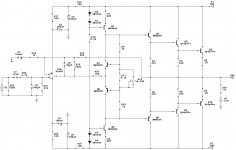
Unfortunately, this schematic in this form or gives distortion due to the small quiescent current of the output transistors, or can easily burn out if you try to increase the current. You can increase quiescent current of the output transistors, if you install a resistor 100 ohms or more in series with the diodes 1N4148. You should increase the value of the resistors R1, R2 R5 R6 to 100 ohms, and thus you will increase the stability quiescent current transistors Q1Q2.Ok, it might be termal runaway but the transistors are cold.. I will put the 1ohm resistors and see..hope it will work. also i dont have the diodes like in the schematic.
What is the use of them?
http://www.diyaudio.com/forums/atta...p-amp-based-amplifier-img_20170109_000654.jpg
Generally speaking, this type of output stage is very unfortunate. It gives a lot of distortion. You'd be good to get rid of it, replacing it with a conventional three-stage emitter followers.
The Marshall 8008 is a much more conventional op amp driven amp.
It uses a TL072 and triple level amplification. The schematic is on eserviceinfo.com
T6 and T15 are VI limiter transistors, not strictly necessary.
Would use the same parts as you have but wired up differently, plus a couple of small TO92 predriver transistors and some TO220 driver transistors.
It is successful commercially, so it must be somewhat stable, even if it only has 0.33 ohm emitter resistors. It does have a Vbe multiplier TR5 on the heat sink to pick up the heat and collapse the base spreader voltage appropriately for collapsing Vbe due to heat.
Last edited:
Rod Elliott's p3a uses same output stage and I've read lot of good about it. But in hia design there are resistors on collectors on the power transistors no on emitters. Why would this design distrot.
I will pit the 1ohm resistors and a pot between the bias diodes and hopefully it will work fine. Thanks guys
I will pit the 1ohm resistors and a pot between the bias diodes and hopefully it will work fine. Thanks guys
Yes, you're right, this schematic better. But output voltage poweramp, which used the front-end opamp and output followers, limited output voltage of opamp. The output voltage of opamp does not exceed 13 V. This is not enough.Something a bit more stable.
Here: #11 I offered the schematics, which allows you to use the front-end of opamp and obtain to output the voltage of any value. This output voltage depends on the supply voltage VAS, and is not limited to the voltage of power supply of opamp. Because the VAS in that schematics adds their gain (not less than 46 dB @ 20k) to strengthen opamp (about 60 dB @ 20k), depth NFB @ 20k can reach 70 - 80 dB. Amplifiers with different schematics did not always achieve such depth of NFB.
Yes, but your schematic had 45 parts even without having a zobel network and a speaker RF limiter coil. The op amp LT1122 you speced is surface mount in stock here, whereas NE5532 andYes, you're right, this schematic better.
Here: #11 I offered the schematics, which allows you to use the front-end of opamp and obtain to output the voltage of any value.
TL072 & TL082 can be bought DIL package, through hole. I built a whole amp channel with no op amp for 35 parts.
If the OP uses his hi power up amp IC he could build the marshall 8008 without the whole predriver stage. Jerlusoo's is okay but the resistor values are set up for a 20 v power supply.
I can't get a datasheet on the Mitubishi 5520. But if the intersil EL5220 is anything close, it has a slew rate of 12v/usec. Anything that fast might be oscillating in the RF band. for op amps over 5 v/usec slew rate I've found a 33 or 47 pf disk capacitor is necessary between output and input minus to short out the gain at the high frequencies.Why, there are NO errors in the schematic, the op amp is Mitsubishi 5220 (+-25v max) I use +-20 rails. What might be the problem.. This js pretty frustrating, and Im not soo experienced to figure it out.
I had build Rod Elliott's preamp with this Mitsubishi 5220 and it sounded way better than TL072
I have two of them from my old Pioneer deck made in Japan
I have two of them from my old Pioneer deck made in Japan
I took the model of opamp only because in the simulator there is no model that looks more like the AD744. You can also use all the mentioned opamp, with the exception of the 5532, because its input stage (LTP) has no resistors in the emitter circuit and gives a larger distortion when this opamp used in poweramp. But by 20 dB will decrease the depth of NFB on 20K and will increase distortion. You should use a good opamp to improve results.The op amp LT1122 you speced is surface mount in stock here, whereas NE5532 and
TL072 & TL082 can be bought DIL package, through hole.
Try to understand me correctly. If you want to build a good amplifier, you should invest in it. As we say: fish cheap - fish soup tasteless. From my side, I tried to simplify the schematic of my amp as I could. I won't be able to build this amp with fewer parts. But it gives only 0.001% at a frequency of 20K as in the simulator and in hardware.Yes, but your schematic had 45 parts. I built a whole amp channel with no op amp for 35 parts.
About me proposed schematics. You need to put the coil on the output of the power amp to eliminate a capacitance load of the loop NFB, but Zobel for stability is not needed. Zobel must be placed parallel to the load, after the coil.even without having a zobel network and a speaker RF limiter coil.
Last edited:
- Status
- Not open for further replies.
- Home
- Amplifiers
- Solid State
- Hi-Fi OP-AMP based Amplifier?!