Hi,
I am starting a new thread to help myself and others planning to use the Beaglebone Black with Hermes-Chronus(+Rhea) cape and OPUS DAC kit.
As of now we are all awaiting a manual/How - to- documentation from TPA.
I have all the boards with me for past 3 days (except Opus - on the way).
I am looking forward to hear from you all.
First I will look for accessories I need in addition to the one provided in Kit. Stacking is not an option with OPUS and Chronus board.
U.Fl connector is not an option with OPUS either ,so need to have jumper cables. Getting some for Arduino .2.54mm size connector.
Not sure how many power supplies I need to have?
This might be a good start..
http://www.diyaudio.com/forums/twisted-pear/272053-hermes-bbb-botic-cape-beaglebone-black-10.html
Last edited by a moderator:
Thanks for starting this thread. I too am interested. I have a spare Opus (v1.0) and was hoping to use it in a similar configuration.
A simple block diagram with (BBB, Chronus, Opus etc.) with signal types connecting them would help me understand immensely. A simple question, showing my ignorance: Is it i2s all the way from BBB to Opus?
I know Opus v1.0 takes i2S in... but will it work with re-clocking scheme implied here?
Cheers,
Ryan
The simplest and best way to to wire the Cronus to the opus will be to orient the digital output of the Cronus close to the digital input of the Opus - then just use short (1 or 2 inches if you can) hookup wire between the modules - one for GND,BCK,LRCK(D1 on Cronus), Data(D2) on cronus. You will then use it as you would any other source with Opus.
Cheers!
Russ
Cheers!
Russ
How about the powersupplies Russ? What type of power you recommend for Hermes and Cronus?
I guess Hermes can draw power from BBB ?
I guess Hermes can draw power from BBB ?
Hermes-BBB can draw its power from BBB or it can supply power to the BBB - but not both. There is a 5V terminal if you wish to use a normal 5V (capable of at least 1.5A) supply - otherwise you simply use the barrel connector power input into the BBB as usual.
Cronus take 5V input as well (7V absolute max) - You will not want to power the cronus from the same supply as the BBB. I would supply it from the same digital supply you use for the Opus.
Cronus take 5V input as well (7V absolute max) - You will not want to power the cronus from the same supply as the BBB. I would supply it from the same digital supply you use for the Opus.
Last edited:
Thanks Russ. Opus has two 5V regulators? on board and has to get supply of at least 7.5 V ( from opus manual).So it has to be two separate supplies since Cronus has an absolute Max of 7 V?
What would be the power draw for Cronus board?
What would be the power draw for Cronus board?
Which opus version do you have? In any case the regulators on the opus are LDOs - they should be fine to go as low a 6V input.
Of course if you like you can just use a seperate 5V supply for the Cronus. The choice is yours. The cronus will only consume < 200ma with most clocks (the type we supply). It just depends on the clocks you choose to use with the Cronus. You can estimate the power draw of the cronus by taking the current of the clocks and adding ~50ma. That will get you pretty close.
Of course if you like you can just use a seperate 5V supply for the Cronus. The choice is yours. The cronus will only consume < 200ma with most clocks (the type we supply). It just depends on the clocks you choose to use with the Cronus. You can estimate the power draw of the cronus by taking the current of the clocks and adding ~50ma. That will get you pretty close.
Great , mine is Opus V2.1. I guess Cronus has no on-board regulators?
Is both LDO on opus are 5V? I thought WM8741 digital supply was 3.3V?
Is both LDO on opus are 5V? I thought WM8741 digital supply was 3.3V?
Last edited:
Great , mine is Opus V2.1. I guess Cronus has no on-board regulators?
Is both LDO on opus are 5V? I thought WM8741 digital supply was 3.3V?
There are two regs on Opus - one is 5V(analog) one is 3.3V(digital) they are LDOs and an operate with as little as 300mv headroom - so 6V input to both is just fine - or 4V into just VD and say 6V into just VA.
Read the first page of the Cronus thread - yes it definitely has a regulator - 3.3V 🙂 5 - 6V is recommended input with 7V being the absolute max.
Last edited:
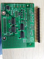
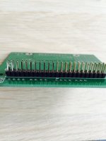
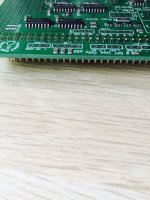
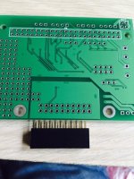
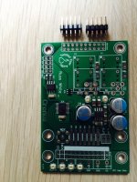
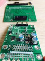
Russ I have the capes for almost a week now and has no idea how to connect them together. Can you please help me out. I am pretty sure it is not complicated but no idea how to connect the boards together.
Just test fit the Hermes headers (on hermes-bbb and Cronus) the way you will want the boards to stack (look at the many photos) then solder the Hermes headers after you are happy.
If you want to use terminal blocks on Cronus solder them on the bottom of the Cronus.
The select the 2:1 (for 45/49Mhz clocks) or 1:1 (for 22/24Mhz) clock divider by installing a jumper at one of the two places.
Cronus datasheet is almost finished. 🙂
For the Hermes-BBB I will post the schematics.
Give everything a test fit - and if you need more help we can get it sorted.
Last edited:
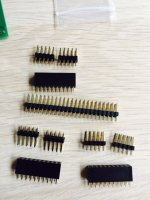
What all mistakes can possibly happen with alignment of headers on Hermes ? I remember reading about some alignment mistakes Twluke made, but never understood what it was
As long as you use the provided (20 pin) male and female headers with the correct number of pins the Hermes header is very straightforward. Test fit and check.
What all mistakes can possibly happen with alignment of headers on Hermes ? I remember reading about some alignment mistakes Twluke made, but never understood what it was
I think his error was with the large green terminal blocks, not the headers.

Do you have a 2 x 10 male pin header or just the two 2 x 5?
EDIT (nevermind I confirmed with Brian that some of the kits are packaged this way - 2 pieces of 2 x 5 is just fine)
EDIT (nevermind I confirmed with Brian that some of the kits are packaged this way - 2 pieces of 2 x 5 is just fine)
Last edited:
You are all set on the hermes - I tend to prefer to keep the male headers on the same sides - so I would put the put the male hermes pin headers on the bottom of the hermes and the female on the top of the Cronus.
Cheers!
Russ
Cheers!
Russ
these are all the headers,that came with boards.Do you have a 2 x 10 male pin header or just the two 2 x 5?
Plus one 2x4 header which is not in the picture
Attachments
- Status
- Not open for further replies.
- Home
- More Vendors...
- Twisted Pear
- HermesBBB-Cronus-Opus