Thanks Tim for your schematic I dont feel that your toplolgy will work I did ask for 30 watts or more !
I have got a problem with my scanner at the moment so can not put my proposed solution on as a schematic at this time !
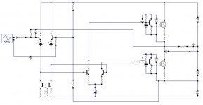
However I will say that the inputs are a differantial pair with opto isolator transmitter diodes in the collectors these are then connected to totem pole darlington transistors with the receiver transistors connected to the bases of the darlingtons
I will try to get this on line this weekend !!!
I must stress I have not yet made the amp its only a design exercise at the moment
there will be stability problems to be sorted I am sure !
At this time I must say I had not thought of the solution when the challange was made but must say I have been stimulated via the challange to think about it on my dailey 3 hour commute to work and back
regards Trevor
I have got a problem with my scanner at the moment so can not put my proposed solution on as a schematic at this time !
However I will say that the inputs are a differantial pair with opto isolator transmitter diodes in the collectors these are then connected to totem pole darlington transistors with the receiver transistors connected to the bases of the darlingtons
I will try to get this on line this weekend !!!
I must stress I have not yet made the amp its only a design exercise at the moment
there will be stability problems to be sorted I am sure !
At this time I must say I had not thought of the solution when the challange was made but must say I have been stimulated via the challange to think about it on my dailey 3 hour commute to work and back
regards Trevor
Re: Here is a Challange
DC coupled - so no transformers or opto couplers !!!!
latala said:.................. Could any of you design a Dc coupled amplifier using NPN devices only !!!
Target power is 30 watts rms or more in 8 ohms at less than 0.1 % distortion midband
................
DC coupled - so no transformers or opto couplers !!!!
Poynton
I have all ready stated you can use opto or any device all that you can not use is a PNP device!
When I issued the challenge I had no Idea what the solution would be and to be honest still dont !!!
I have suggested opto,s as merely 1 solution
The use of opto .s would give an absoulute dc coupled effect any drift in output would be corrected by the diff pair
So come one where is your solution
Regards Trev
I beg to differ, by design it's trivial to take a differential output from the second stage and use a push-pull class-ab output stage.
I did say the output stage needed revamping, being only one of the simplest NPN followers possible.
There nothing stopping it from going within a couple volts of either rail.
I did say the output stage needed revamping, being only one of the simplest NPN followers possible.
There nothing stopping it from going within a couple volts of either rail.
latala said:The other one by steve eddy is interesting ! and very unexpected
lots of iron though!
Well sure. Why do you think Popeye ate his spinach? 😀
se
TIm_ X
Please do not get me wronge I am not Knocking your design
However I feel that to get a practical design your output stage leaves somethingto be desired ! From what I can see it would have to be class A. Nice but not practical , now if it was Ab that would be a different thing!
The front end and driver of your design is ok, but as I see it would be the driver outputstage where we have a problem .
Please think again you at least have the courage to put your ideas forward for which I thank you .
The Idea is to see where an alternative/restrictive design concept would get us
Regards Trev
Really guys, there's a ton of designs that fill this requirement.
The stupidest of them would be the Son of Zen - just throw some feedback around it for a distortion spec.
Other ones? Balanced versions of the PLH, ZV4 or ZV9, without the coupling caps.
Don't like that? I have a swell circlotron...
The stupidest of them would be the Son of Zen - just throw some feedback around it for a distortion spec.
Other ones? Balanced versions of the PLH, ZV4 or ZV9, without the coupling caps.
Don't like that? I have a swell circlotron...
Workhorse I like your solution I thik it has potential !!! You have implimented a solution at the front end that to be honest I dont think I would have come up with .
Sorry I called you Trojan erliear got a little confused with your label.
Thank you Mr Pass for your suggestions and while I have built and do like class A designs I feel they are always difficult because of heat issues etc .
However I must admit that I have not listened to any of your designs
I have looked at some of your work but have not come across the Circlotron and will endeavour to find it .
I don,t think I was specific enough when I made the challenge but as ever the forum is a great learning aid in that it makes one think and attempt to be logical it not only knowing what are the answers but also what are the correct questions to ask
regards Trev
latala said:Workhorse I like your solution I thik it has potential !!! You have implimented a solution at the front end that to be honest I dont think I would have come up with .
Sorry I called you Trojan erliear got a little confused with your label.
I just accepted your challenge and now rest is history.🙂
I like it, looks like mine but without the first stage and without component values to expose its lack of polish.
Nelson I have tried in vain to find a copy of your circlotron would you please be kind enough to tell me where to find it or please repost!
It sounds fascinating ?
I am sorry to say that my combined scanner/printer is not working at the moment so I can not attache or createany thing sorry for the delay
Regards Trevor
It sounds fascinating ?
I am sorry to say that my combined scanner/printer is not working at the moment so I can not attache or createany thing sorry for the delay
Regards Trevor
Hello latala, I suspect that Dear Mr. Pass is referring to the EV Circlotron tube amp. Don't hold me to this, as I can't read minds from close up, much less the distance between Mr. Pass and myself. If this is what he refers to, here's a link for some information:
http://circlotron.tripod.com/
Peace,
Dave🙂
http://circlotron.tripod.com/
Peace,
Dave🙂
I think Nelson has a solid state cirlotron I have seen the Wiggens EV unit and consider it a wierd but wonderfull beast!
However as much as I do like tubes or as we in the Uk call them valves, I have a matter of policy always gone the semiconductor/solid state route.
I am still working on my solution and as agreed with the Trojen
i feel that his solution is worth looking into .
When I created the challenge I was not specific enough I should have stated class b/ab output as again I feel that class A is not really practical due to heat etc
Thank you very much for your time and input
regards Trevor
The circlotron in question has not been released. It's still a
Secret Circlotron. Nevertheless there are other circlotron
examples.
Secret Circlotron. Nevertheless there are other circlotron
examples.
Ok Mr. Pass, are you keeping this with your super collider. What kind of experiments are you doing for audio improvement. You don't have a secret upper hand over the other designers, do you?!😀 😉
Peace,
Dave
Peace,
Dave
I'm not sure how or why an all-N amp is supposed to be a challenge; this seems more like a tempest in a teapot. Bear in mind that all tube amps qualify. And if it's solid state you have in mind, there's no reason you can't capacitor couple things (even if some people break out in hives at the very thought).
Solid state Circlotrons are simple. I used that topology for the New-Tron.
Grey
Solid state Circlotrons are simple. I used that topology for the New-Tron.
Grey
I have searched for your New-Tron. but can not find it please advise ?
I know re all valve amps are npn etc
But Iron is expensive and capacitors are considered old hat I just wanted to see if there was any solid state npn dc coupled to the spk! amplifier out their in this wide wide world ?
regards Trev
I know re all valve amps are npn etc
But Iron is expensive and capacitors are considered old hat I just wanted to see if there was any solid state npn dc coupled to the spk! amplifier out their in this wide wide world ?
regards Trev
If you think capacitors are 'old hat,' don't look at the schematics for Nelson Pass's front end gear.
Or mine, for that matter.
The New-Tron:
http://www.diyaudio.com/forums/showthread.php?s=&threadid=78734&highlight=
If you don't like the front end(s), stick another one on. Doesn't matter to me.
Grey
Or mine, for that matter.
The New-Tron:
http://www.diyaudio.com/forums/showthread.php?s=&threadid=78734&highlight=
If you don't like the front end(s), stick another one on. Doesn't matter to me.
Grey
this seems to be an improved topology (push pull emitter cascode) of Audiophonics Zeus version aboutBy NPN only, are you being literal in that you only want NPNs as in bipolar NPNs, or does that also include N-type FET devices? If so, here's a concept for you.
An externally hosted image should be here but it was not working when we last tested it.
se
http://www.diyaudio.com/forums/solid-state/42259-zero-feedback-impedance-amplifiers.html
- Status
- Not open for further replies.
- Home
- Amplifiers
- Solid State
- Here is a Challenge