The problem will still be how to get only 3x gain.
That's exactly why I suggested the 12B4, whose μ is all of 6.5 . 😉 Resistively loaded triodes yield a voltage gain that is approx. μ/2. The 12B4's low RP will make the gain a bit more than μ/2, but 11 or 12 dB. of linear gain and no loop NFB complications should be highly suitable to the requirements under discussion.
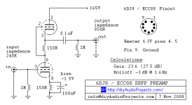
@PCL200 - Then 6DJ8, which I think is the same as the ECC88, is the tube I was thinking about using. But I've seen designs with >200v power supplies with this tube. The data sheet I found shows plate voltage transfer functions at 90v, 150v and 200v. Do you think this will still work well at lower voltages?
Yes, they will. Why they show transfer functions for 150V and 200V in datasheets is a bit of a mistery to me since Va max = 130 V. They were designed for cascode operation in the first stage of TV tuners so the two triode sections had to share the available B+ (something like 200 V in Europe).
But the gain will be something like 15 to 20 x (depending on circuit) so maybe too high for your application.
Three examples. If you skip the cathode capacitor in the first schematic, the gain will be about 16 x:
Attachments

@rongon - that balanced output looks interesting, but wouldn't it be very sensitive to power supply noise?
I don't see why it should.
6DJ8 differential pair has decent PSRR.
MOSFET source followers have decent PSRR.
It's not a high gain circuit, and it will be accepting line level signals at the inputs, so SNR shouldn't be as critical as something like a phono preamp (where input signal is very low amplitude and there's lots of gain).
A 200V Maida regulator could be rigged up if you're worried about PSU noise.
I've found that a solid-state rectified, choke-input supply can work well (use two or three stages of RC decoupling to filter out ripple).
Meant the output in post #17. The circuit in #19 is more what I was thinking.
Took me a while to catch on. The common cathode into MOSFET split load phase splitter would have no more problem with power supply noise than a typical common cathode amplifier.
--
All that said, Eli's suggestion to make a diff-pair 12B4A is also a nice idea. Gain should be 2x to 3x at most. I think THD might be pretty high unless you put a CCS in the diff tail. Gain will drop and THD will rise into that 2.2k ohm load, but it looks like it should work great with the CCS — without negative feedback.
Another low gain tube you might want to look at is the Russian 12P17L. It's plug ugly, but it's a good indirectly heated pentode that works well triode-strapped. It uses a loctal base and a 12.6V heater.

Some specs from Ale Moglia: 12P17L – Bartola(R) Valves
12P17L is touted as a poor man's 4P1L but it's not nearly as linear as that directly heated pentode.
--
Last edited:
All that said, Eli's suggestion to make a diff-pair 12B4A is also a nice idea. Gain should be 2x to 3x at most. I think THD might be pretty high unless you put a CCS in the diff tail. Gain will drop and THD will rise into that 2.2k ohm load, but it looks like it should work great with the CCS — without negative feedback.
A quality tail constant current sink (CCS) makes for long "length" and forces AC balance between the 2 bottles. IMO, the CCS is essential.
MOSFET source followers DC coupled to the 12B4 plates dispose of the impedance mismatch issue and don't increase the count of caps. directly in the signal path.
12B4 distortion, when resistively loaded at 3X RP, is very low. The "usual" α = μ(RL/(RL+RP)) formula for gain applies, when both I/Ps of the differential pair are driven.
Well, I'm learning a lot digging into all your proposed ideas. The concern I have with using a design that needs to be AC coupled to the Purifi amp module is that the size of the capacitors is quite large to provide reasonable low frequency performance into a 2.2K load. Using high quality film caps would be prohibitive.
Of course, I could add another op amp stage to provide a higher impedance load to the tube buffer.
Would it be reasonable to consider using a high quality opamp (or two) ac coupled directly to the LTP plates?
Of course, I could add another op amp stage to provide a higher impedance load to the tube buffer.
Would it be reasonable to consider using a high quality opamp (or two) ac coupled directly to the LTP plates?
The concern I have with using a design that needs to be AC coupled to the Purifi amp module is that the size of the capacitors is quite large to provide reasonable low frequency performance into a 2.2K load. Using high quality film caps would be prohibitive.
Let's see; working into 2.2 Kohms, 15 μF. coupling caps. will be satisfactory. $8.75 is Michael Percy's price for a 250 WVDC/16 μF. Solen. Bypassing that item with a $1.25 0.47 μF./400 WVDC 716P "orange drop" will yield quite acceptable performance, without sending a builder to the poor house. $10 per differential leg to avoid complexity seems reasonable enough to me. Of course, substantial physical bulk would be present.
I'm not familiar with the myriad of items available in the integrated circuit catalog. Is a high I/P impedance/low O/P impedance differential (at both ends) line driver IC available? Such an item, if available, would be ideal for buffering the "hollow state" LTP.
I agree that the Solen caps might be a decent option, particularly bypassed with one of the really high quality caps available, but as you stated, this takes up a fair amount of space. Not out of the question though.
I haven't heard the term "hollow state" before. Does this refer to a LTP with no load (other than the plate resistors)?
I was thinking of using one Sparkos Labs discrete op amp in a non-inverting unity gain configuration connected to each plate of the LTP through a coupling cap. The current to the op amp is typically 4.5uA. These op amps have plenty of drive (up to 40mA).
"Hollow State" is a nickname for vacuum tube electronics ('hollow' as opposed to 'solid' state).
The problem with an op amp DC coupled to the plate of a tube is that there will be at least 60V DC at the op amp input, and well over 100V at power up. If the B+ is 200V loaded, it may be higher unloaded. While the tubes are warming up, they won't be drawing current, so their plates may be up at full B+ potential for a second or so. Those kinds of voltages fry typical solid state devices designed for use with +/- 15V DC rails. Just something to think about.
The 12B4A has a plate resistance (rp) somewhere around 1000 ohms with 34mA current being dragged through it. That means the Zout could be as low as 800 ohms. Is that low enough to drive a 2200 ohm load? It could be.
To make a 12B4A LTP, the triodes will have to be biased with at least 10mA plate current (Ip), and preferably more. If you bias the 12B4A at more like Ip = 20mA, you might be able to drive the amplifiers from the 12B4A plates (and output coupling capacitors, of course).
12B4A uses twice as much heater power than 6DJ8, and typically three to four times more plate current.
The reason I brought up the idea for a 6DJ8 LTP DC coupled to MOSFET source followers finished off with NFB is that it would use less current in both the plate and heater circuits, give you a really low Zout, and also be very linear. The plate resistors wouldn't have to be wirewound 7W types (they could be 2W metal film), which would use less space and should be cheaper. Of course the circuit uses NFB, which some don't like in their vacuum tube audio stuff. But in this case the NFB would be applied to only one gain stage in a DC coupled circuit with no transformers or inductors.
If you don't mind using more current in your machine, then the 12B4A differential can get you there with no loop NFB. The price is bigger transformers and higher wattage resistors. Probably not a big deal.
--
Last edited:
I was thinking of using one Sparkos Labs discrete op amp in a non-inverting unity gain configuration connected to each plate of the LTP through a coupling cap. The current to the op amp is typically 4.5uA. These op amps have plenty of drive (up to 40mA).
That should work; AC coupling between the tubes and buffers combined with DC coupling between the buffers and Class "D" power O/P device, instead of the other way around. This configuration makes a "boutique" coupling cap. comparatively reasonable. Frankly, a 716P or Soviet surplus K40 PIO is plenty good.
Ah, that makes sense re: "hollow state".
I was assuming that the op amps would be AC coupled, but your point about over voltage on start up is something I hadn't considered. I think this could be dealt with by using zener protection diodes, and possibly also turning on the heater supply before the main supply.
I'd like to avoid adding an additional power supply voltage. I already have +/- 65v going to the buffer board for the Purifi module, and was assuming I'd add a cap mx circuit to provide further filtering for the tube circuit, which would cut the voltage by a few volts. I also have a +/- 12v op amp supply. I'll have to add an extra supply for the heater voltage, or use a DC-DC converter to draw it from the +65v supply (if it's not too much current, that's probably what I will do).
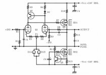
I'm intrigued by the Borbely design which is along the lines of what you are talking about but using +/- power supplies and NFB to adjust DC output. This circuit is designed around the 6DJ8, so it seems like it could be adjusted to use higher rail voltages and lower current through the MOSFETS (it was originally designed as a power amp).
I think there are several options with this circuit to generate both output phases. Use the 'source-o-dyne' output you proposed, add an op amp stage after the mosfets to generate both phases, remove the current mirror and tap off both plates to either replicate the source follower for both phases or replace with op amps as I suggested earlier.
I'm not too concerned about cost or complexity (although I do have some real estate limitations with the enclosure I'm planning to use). My main priority is to get the highest audio quality while adding some of the triode sound characteristics.
I really appreciate yours and Eli's council on this. I'm a total neophyte with tubes, and haven't really done any analog design in many decades and I think I've forgotten almost everything I knew.
I was assuming that the op amps would be AC coupled, but your point about over voltage on start up is something I hadn't considered. I think this could be dealt with by using zener protection diodes, and possibly also turning on the heater supply before the main supply.
I'd like to avoid adding an additional power supply voltage. I already have +/- 65v going to the buffer board for the Purifi module, and was assuming I'd add a cap mx circuit to provide further filtering for the tube circuit, which would cut the voltage by a few volts. I also have a +/- 12v op amp supply. I'll have to add an extra supply for the heater voltage, or use a DC-DC converter to draw it from the +65v supply (if it's not too much current, that's probably what I will do).
I'm intrigued by the Borbely design which is along the lines of what you are talking about but using +/- power supplies and NFB to adjust DC output. This circuit is designed around the 6DJ8, so it seems like it could be adjusted to use higher rail voltages and lower current through the MOSFETS (it was originally designed as a power amp).
I think there are several options with this circuit to generate both output phases. Use the 'source-o-dyne' output you proposed, add an op amp stage after the mosfets to generate both phases, remove the current mirror and tap off both plates to either replicate the source follower for both phases or replace with op amps as I suggested earlier.
I'm not too concerned about cost or complexity (although I do have some real estate limitations with the enclosure I'm planning to use). My main priority is to get the highest audio quality while adding some of the triode sound characteristics.
I really appreciate yours and Eli's council on this. I'm a total neophyte with tubes, and haven't really done any analog design in many decades and I think I've forgotten almost everything I knew.
Attachments
The uploaded "El Cheapo" power amp schematic shows a long tailed pair (LTP), AKA differential gain block, and tail CCS driven only at the inverting I/P. Here, loop NFB is applied to the non-inverting I/P.
This new project would apply the "balanced" I/P signal to both the inverting and non-inverting I/Ps.
BTW, the resistors in series with the tubes' control grids are known as "stoppers". They suppress parasitic oscillation. Good construction practice mounts grid stoppers as close as can be to the tube sockets. The idea is to minimize the metal mass that can function as an antenna. Use of carbon composition resistors in the stopper role is motivated, in part, by their non-metallic nature. Stoppers are frequently employed on the gates of FETs too.
Attachments
The circuit of #19 looks pretty good for you. I would have a small negative supply and a CCS for R17. The FB will reduce distortion and set the gain. If your valve magic is the distortion then this circuit will not produce much second harmonic. If its just to look the part that's fine. You could replace the MOSFETS with cathode followers to go more valve and loose HS1 and HS2.
Last edited:
baudouin0 raises a good question: Why use tubes?
Because...
- You want some of that 'tube sound'? If so, what exactly is 'tube sound'? Added 2nd harmonic distortion? Or...
- Do you want to try out some hot glowing tubes, and you want to make your added gain stage as transparent as possible? (I.e., no warm and gooey 'tube sound', just low distortion audio using tubes?)
???
FWIW...
For a bit of 'tube warmth' you could take the circuit in post #19 and use cathode followers instead of MOSFET source followers. The tube cathode followers would load down a bit into the 2.2k ohm load, which would add a bit of tube sound. Whether that's a good thing or not depends on your taste in audio playback.
A 12B4A LTP run with high current (like 30mA per tube) would have lower than 1k ohm output impedance, which would drive your 2.2k ohm load well enough to get by, but maybe load down just enough to sound noticeably 'warm'. If you buffer the tubes' outputs, you might end up with 'just' clean gain. If clean gain with hot glowing things is what is desired, then the 12B4A LTP into the honkin' semiconductor buffers would be very cool, I think. Just depends on what the design goal is.
I built a little line stage with a single 6DJ8 in it, wired up as an 'anode follower' (local plate-grid feedback) set to 3X gain. There's no output buffer in it. It has a very low B+ of 150V. Each 6DJ8 triode draws only about 3mA plate current (Vp = 60V, Ip = 3mA, yellow LED in cathode gives Vk = 1.8V, Rp = 33k). It's transparent into a 100k ohm load, but it loads down into a 10k ohm load, giving a bit of 'tube sound' to my currently all solid-state setup. (Because the output cap is only 2.7uF it causes the feedback loop to work too hard at low frequencies, giving the line stage a kind of 'tubey' looseness in the bass. Otherwise it's quite transparent, adding/subtracting nothing I can hear.
I also tried it with a 6N1P, which biases up cooler than the 6DJ8 (B+ rises to 160V, Ip = 1.67mA, Vp = 105V, Vk = 1.7V). With the 6DJ8 the line stage sounds cleaner ('leaner') but with the 6N1P it sounds more 'tubey' ('warmer').
I like the sound from the line stage added after my phono preamp, adding a nice bit of fatness and warmth (for lack of better terms) to my vinyl playback, so I use it only for that. I like it better for this with the 6N1P, maybe because I like some added lower order THD in my vinyl playback. Perhaps I have bad taste in audio playback.
I tried this line stage inserted after my DAC (output reduced to 1Vrms max out to level match) and I did not like the ever-so-slightly diminished clarity and the looser, somewhat compressed-sounding low frequency response I heard. Therefore my digital sources don't go through the tube stage.
It's just a temporary experiment, a way to acquaint myself with the 'sound' of a medium-mu triode anode follower circuit in isolation. I'd put 4.7uF or larger output film caps in, but the chassis is far too small for that. I might try a pair of 10uF bi-polar electrolytics as an experiment, if I can find some rated for 150V or higher. Or maybe build a new anode follower-based line stage with switchable feedback resistors to adjust the gain, and some kind of buffer on the outputs. If buffered, I might use a 12AT7 for its higher gain (and I have a lot of 'em), so I can wrap more NFB from output to input. Just to see if I like that or not.
Sorry for blabbing like that. I got a bit carried away...
--
Yep I agree. You need to decide whether you just want some tubes and want the pre-amp to be blameless and match the .001 distortion of the class D -or you do wish to add distortion to give a more tube sound - what that maybe. My point is that the LTP with the balanced o/p will produce mainly 3rd harmonic which is not so nice. You really want 2nd harmonic i.e. a asymmetric non-linearity. A 12ax7 makes a lovely pre-amp for a guitar clean feed - really depends on what you wish. If you want low distortion go with a high gain LPT with a CCS tail and a MOSFET or cathode follower and use feedback to get the gain to 10x.
Last edited:
You want some of that 'tube sound'? If so, what exactly is 'tube sound'? Added 2nd harmonic distortion?
FWIW, I think there are as many definitions of "tube sound" as there are listeners. 😉 Again FWIW, my definition of tube sound is fundamentally honest, with the tiniest amount of added 2nd HD to take the "icy cold edge" off. It's shocking (NOT) that I like 12B4s and 6SN7s.
Yup, exactly. I completely agree with everything baudouin0 and Eli just posted.
FWIW, the classic 'cathodyne' push-pull power amp driver topology (such as in post #17) makes a nice combination of 'single-ended tube sound' and balanced 'cleanliness'.
In the circuit in post #17, the first stage is a single 6DJ8 triode used as a common cathode amplifier (single ended triode), which will operate with reasonably low distortion. With up to a volt of signal input almost all its distortion will be 2nd harmonic. The second stage is a MOSFET split load inverter (unity gain) which runs with extremely low THD at these low-ish signal levels. So you get generally low distortion and almost all of that distortion will be 2nd harmonic—the 'nice' and 'tubey' kind.
Once you go to an LTP with balanced inputs, you get the even order harmonics cancelling (including 2nd harmonic, of course) leaving you with almost all odd orders. At that point you want to make sure the tube you use generates almost entirely even order HD, so that when those get cancelled out all that's left are low residuals of odd order harmonics. The 6SN7 is generally great for this, as it generates low levels of HD in general, and low levels of odd order harmonics in particular. Eli has recommended the 12AT7 for use in LTP configs, because the 12AT7 has a lot of gain, albeit at higher THD than other tubes, but 2nd harmonic predominates. Used to make a LTP, the high levels of 2nd harmonic distortion cancel, leaving only low levels of odd order harmonics = low THD with lots of gain.
But in this case we do not want lots of gain, so I expect that's why the 12AT7 has not been mentioned.
I don't have experience with the 12B4A tube type, so I can't say if it tends to generate much in the way of 3rd harmonic or higher odd harmonics. If 2nd and 4th harmonics dominate its distortion spectra, then that would be a great choice for a low gain, relatively low impedance (for tubes, anyway) LTP.
The 6DJ8 type does tend to generate more 3rd and 5th harmonics in its distortion spectra than many other types of triodes. It's best to choose 6DJ8 for uses where that won't be a problem. An LTP using 6DJ8 might have higher 3rd hamonic distortion than you'd like. But wrap some NFB around it and all the HD goes down, including odd orders. So 'it depends.'
Everything is a compromise between this and that.
--
I appreciate all your input and ideas. My main goal is to get a bit more 2nd harmonic distortion without compromising the detail and airiness. I'm not completely sure that is possible, but we'll see.
My design has somewhat limited space for the input buffer. I also want to design it so that I can maintain compatibility with the standard input buffers available from other vendors so that if I'm not happy with my own design, I can try alternatives without re-engineering the whole amp, and also so I can use the board with the standard Hypex SMPS supply that most people use. I'm building my first two monoblocks with a linear PS, but may build additional ones using the SMPS.
I've got about 85mm x 115mm to play with (single channel) and have power supply voltages of +/-65V unregulated, +/-18V unregulated, and +15V regulated, referenced to the -65V input (for the Purifi module gate drive circuitry). The input buffer board is responsible for generating a regulated +/-12V supply (from the +/-18V) for the Purifi module.
So I need to figure out how to run the tube circuit with these supplies.
I'm going to try prototyping a couple of designs to get a better feel for how the tubes work, using some of the concepts we've discussed. I think your points about using a single tube instead of a LTP to get more 2nd harmonics makes sense.
Thanks again for your help.
Another idea has bubbled up from the depths. 😉 Assuming the "balanced" upstream signal source has a low O/P impedance, use a transformer to convert differential to "single ended. A simple resistively loaded common cathode 12B4 provides the necessary gain. An IRFBC20 MOSFET "concertina" phase splitter is DC coupled to the 12B4's plate. The splitter yields an amplified differential signal. Use whatever highly competent SS buffers (IC or discrete) are found suitable to drive the Class "D" power O/P device, with the amplified differential signal.
Sowter's model 3603 looks like it could handle the balanced to single ended conversion.
Using a 2.2 Kohm 12B4 plate load resistor will hold stage gain down and promote the generation of the desired 2nd HD dose.
Sowter's model 3603 looks like it could handle the balanced to single ended conversion.
Using a 2.2 Kohm 12B4 plate load resistor will hold stage gain down and promote the generation of the desired 2nd HD dose.
- Home
- Amplifiers
- Tubes / Valves
- Help with tube buffer