@koifarm - that's a nice looking board. Have you used it with the Purifi module? Would you consider sharing the schematic?
Having looked at the LTP again it has a problem in that only one output is connected to the FB, the other cathode follower is not included - so the distortion is higher - not very symmetrical and complicated. A simple mosfet would be better.
I think koifarm suggestion is much better and drive the module single ended.
The ECC99 is low gain and does not allow FB very much. I changed the first stage for a 12ax7 with distortion is .2% at +/9V input 2k2. The only thing is you would have two channels on one board.
Of course its up to you what you build - we can only make suggestions.
@koifarm - that's a nice looking board. Have you used it with the Purifi module? Would you consider sharing the schematic?
I build it for hypex UCD400 oem modules not for Purifi. But you can use same schematic. I shall look up the schematic and upload it here.
Having looked at the LTP again it has a problem in that only one output is connected to the FB, the other cathode follower is not included - so the distortion is higher - not very symmetrical and complicated. A simple mosfet would be better.
I think koifarm suggestion is much better and drive the module single ended.
The ECC99 is low gain and does not allow FB very much. I changed the first stage for a 12ax7 with distortion is .2% at +/9V input 2k2. The only thing is you would have two channels on one board.
Of course its up to you what you build - we can only make suggestions.
View attachment 882311
Aren't we back where we started? FYI...
In post #14 I posted a single-ended (unbalanced) line stage using a single 6DJ8 per channel, about 3X gain, with low THD.
It would also be possible to use a single 12B4A triode per channel (unbalanced, single-ended) with no NFB and no output buffer.
In port #19 I posted a 6DJ8 differential stage with shunt NFB applied balanced (equal NFB to each side of the diff pair).
It would also be possible to make a diff pair using 12B4A triodes, which would give you about the right level of gain without NFB, and would not need output buffers.
Both are basic 'building block' topologies using triodes. I didn't invent them. I'm showing them for informational purposes, because it looks to me like they would work for you in this situation. There's certainly room for modification, refinement, improvement.
Isn't your signal source balanced? If so, do you want to unbalance it? Or do you want to leave it balanced? IMO, the only thing that would force you to leave it balanced is if you have long cable runs from your source device(s) to the preamp(s).
--
Last edited:
Thank you all.
I do have fairly long cables between my preamp and power amps (about 8 meters), so I would like to keep balanced inputs and would also prefer to drive the Purifi module with balanced, but this is perhaps less important.
Would using a circuit like post #71 and making it fully symmetric (addling NFB from U2 cathode to U4 plate, and adding negative input signal to U3 plate) work ok?
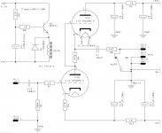
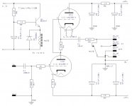
Schematic latest version with 6N28B-V tube in picture below.
For 6n6p/ECC99 tube change pinout and R3 and R4 is 1K.
C1 can also smaller 4,7uF.
For balanced use 2 times the schematic one for + signal and one for - signal.
You can use one mute delay with two contacts.
For 6n6p/ECC99 tube change pinout and R3 and R4 is 1K.
C1 can also smaller 4,7uF.
For balanced use 2 times the schematic one for + signal and one for - signal.
You can use one mute delay with two contacts.
Attachments
Last edited:
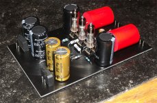
@Koifarm - thank you for posting the schematic.
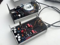
I noticed some nice looking capacitors in your board photo. What kind are those?
I noticed some nice looking capacitors in your board photo. What kind are those?
Obbligato capacitors and amtrans resistors.
Attachments


Last edited:
Attachments

Last edited:
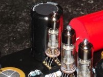
You can solder them direcly to the pcb or solder them to a 8 dip socket and put them in another dip socket on the pcb. The tube last for at least 10.000 houres.
Attachments

Last edited:
Thanks. That makes sense.
I am wondering if I use two copies of the tube buffer/preamp circuit to drive the balanced inputs of the Purifi, will I lose some (or most) of the "flavor" of the tube sound? If so, it might be better to use an opamp differential receiver in front of the tube section and drive the Purifi module single ended.
I am wondering if I use two copies of the tube buffer/preamp circuit to drive the balanced inputs of the Purifi, will I lose some (or most) of the "flavor" of the tube sound? If so, it might be better to use an opamp differential receiver in front of the tube section and drive the Purifi module single ended.
Noise and distorsion in the source signal will not changed by the balanced output. Only interference on the balanced cable is compensated. 8m rca cable is also no problem, so balanced cables is mostly in home use not needed. I did a lot of comparising and could not hear the dfference between 10m balanced and unbalanced line.
Last edited:
You are probably right about the balanced vs unbalanced cable. My DIY preamp only has balanced outputs since that's always what I have used in my systems, and all my cables have XLR connectors. Of course, I could always ignore the negative phase signal in the amp, but it's not hard to build a very clean differential receiver - or potentially use a transformer - if I want to convert to single-ended.
I'm trying to understand the effects from using a differential signal from two tube circuits operating on the out of phase signals. If I understand correctly, even harmonics are generated since the tube has a non-linear transfer function as the signal goes from negative to positive (compressing on one half and expanding on the other relative to perfect linearity).
If the opposite phase input is being processed by an identical circuit, one phase will be slightly compressed and the other phase will be slightly expanded relative to perfect linearity, and the difference between them will be more linear than either signal by itself.
Is this not the case?
On second thought, this would seem to increase the non-linearity since you are taking the difference. But since the peak-to-peak signal through each tube circuit is only half the amplitude (compared to a single-ended design) for the same amplifier output level, maybe this results in approximately the same level of harmonic distortion.

Here is the fully balanced version for you to look at. The common mode rejection ratio is >30dB.

- Home
- Amplifiers
- Tubes / Valves
- Help with tube buffer