The relay shorts the output of the tubebuffer to ground for the first 20 sec after power on.
If you use not the right topology you do not get any coloration, just more distorsion.
I had tube preamp stages that sounded like a opamp(lm4562) with the hypex ucd.
But other stages ad a little warmth and wider soundstage.
I like the SRPP stages with ECC99 or 6N6P-DR tubes. The gain of 11/12 times can be lowered with a serie resistor at the output. Because of the higher output impedance you can also use smaller output capacitor and the load of the tube is lower.
Last edited:
LTP would work too as long as you don't take the differential output (so to get 2nd harmonic). You will loose the lower impedance output so there may be some interaction with the op-amp circuit.
Any imbalance in an LTP will cause some degradation of the cancellation of even-order harmonics. You can deliberately let some imbalance happen to increase even-order harmonics.
Also, no two tubes are exactly alike, even of the same type or within the same envelope, so there will always be at least some imbalance.
One thing you could do is use a resistor in the tail, which acts as a 'softer' (lower impedance) CCS, allowing more imbalance in the LTP, increasing even-order harmonics.
There are many choices. The first order of business is to get the design goals nailed down. I'm still not clear on exactly what the goals are.
How much gain is needed?
What is the load impedance to be driven by the tube stage?
Is clean sound desired, or is a 'tube sound' effect desired?
What power supply is available for use with the tube stage? Is +/-65V DC the only choice?
--
Thanks for all the replies. I'll try to clarify my goals and requirements since they have changed a bit since starting this thread.
I'm assuming I'll take the approach of using both an op-amp buffer and the tube buffer in parallel with a mixing circuit on the outputs. So I'll convert the balanced input to a single ended signal before driving the tube buffer. The output of the tube buffer will feed a mixer which will feed the balanced line driver to drive the Purifi class-D module.
So the primary goal for the tube buffer is to create even-order harmonics without introducing a lot of noise.
Between the input to the buffer and the output to the Purifi module, I need about 10db of gain. The Purifi module reaches full output at about 9.6Vrms across the differential inputs. Since I'll have several op-amp stages at the input and output of the buffer board, it is easy to create the required gain at any point. If there is too much gain from the tube buffer, this can be knocked down a bit in the mixer circuit.
My speakers are fairly high efficiency, so I don't anticipate ever reaching full output. My current speakers are a bit more than 93db/w, but I'm building a set of line-source speakers that will be 98db/w, and being line-sources, the drop off is much less as you get further from the speakers. This is the main reason I don't want too much gain since I want to have at least a little range in my pre-amp volume control.
The drive requirements of the tube circuit are dependent on the mixer which can easily have an input impedance of 25K to 50K.
I want to make the board compatible (from a connector and power supply perspective) to other Purifi buffer boards on the market so I can easily swap in other buffer boards and/or provide this buffer to other DIYers. So the power supplies I have available are +/-65V unregulated, +/-18V unregulated, and +15v referenced to the -65v rail.
The buffer board is responsible for taking the +/-18V and generating a +/-12v regulated supply to the Purifi module, so this will also be available for circuitry on the buffer board.
I was assuming that I'd implement an active capacitance multiplier circuit to clean up the +/- 65v rails for use by the tube circuits. This will drop the voltages down to ~ +/-62v, but will be fairly clean.
It's possible to implement a DC-to-DC converter circuit to get a higher voltage on the board if required, but I'd prefer not to do this since I think it's hard not to introduce noise with such a circuit.
I hope all this makes sense. Thanks.
How much current is available from the unregulated +/-65V DC supply for the tube stage?
(The tube stage is not a buffer per se, since it has gain.)
Where do you plan to get the 6V 1.2A or 12V 0.6A (AC? DC?) for the tube heaters?
Mixer? What kind of mixer?
--
Later...
Looking at the manual for the 1ET400A module, it says the max analog input level is 9.6Vrms, which would mean you'd want to reach that at about 1Vrms from your signal sources = 9.5X gain. A single-ended 12B4A or 6V6-triode would give you almost that. Have you seen all the excitement over diyAudio member Salas' 6V6 line preamp?
6V6 line preamp
Everybody seems to like that one better than the 12B4A line stage that was making the rounds before that.
Yet another 12B4 line stage, or is the 12B4 better than the Grounded Grid.....
There have been numerous 6N6P and 5687 based line stages that yield about 12X gain, which is in the ballpark.
There was a 6SN7 line stage that was popular for a while.
Frank’s 6SN7 preamp/linestage
There are so many ways to skin this particular cat...
--
Last edited:
I was thinking I'd use a switching regulator from the +65v rail for the heater voltage (probably both heaters in series if using dual triodes). The +/-65 rails will be able to deliver plenty of current. I'm using a 1000VA transformer through a CRC filter. The parts I've selected are capable of many tens of amps. At clipping, the Purifi module is pulling less than 10A, and I'll never be playing it that loud.
The mixer is just a resistive summing circuit. I'm not sure if this will be implemented with two ganged pots, or switched attenuator. I'd like to build it so that selecting different "mixes" between the two circuits doesn't change the apparent loudness, so it might be easier to just have a handful of different mix options with selected resistors.
I don't want this much gain because I'll never get past the first few steps on my preamp volume control. With 98db/w speakers, I'll be operating at less than a watt most of the time. The full-scale output on my DAC is 4.6Vrms, and I've got my preamp set up with a gain of 2x, so I can theoretically drive the Purifi module to full volume with no gain on the buffer board. I figured a gain of 10db was a reasonable compromise to use with other setups.
Per your last sentence - yes, it is very confusing for a newbie to figure out what would work best. I suspect I just need to pick one and go for it. Since I enjoy the design process and building as much as the end results, I'd be happy to try again if I'm not satisfied. This is my third monoblock amp build this year.
One advantage of using the Purifi module is that it offers plenty of clean power and I can experiment with different approaches to the buffer board to achieve different results.
You may find the mixer circuit problematic as the phase delays of the valve circuit at 20KHz if they exceed 90deg will affect the frequency response. Some of the valve circuits (not the LTP) invert too. I would just have a simple switch or relay. In my books I would always be designing a blameless amp with as low a distortion as possible valve or not valve. The time I would have distortion is if I was designing a lead guitar amp. I would keep it simple. A switching reg to 12v with the heaters in series should be fine - make sure its rated about 2.5x the current as at switch on the heaters take a lot more current and may cause it to shut down.
Last edited:
Yeah, I wondered if the phase shift would be an issue. I may have to rethink this whole concept. I will probably build the amp first with a simple op amp based buffer circuit and then figure out what I want to do with a tube based design.
I really appreciate all the wisdom you guys have provided.
I really appreciate all the wisdom you guys have provided.
I think if I were doing it I would have an all op-amp path and a all valve path switched by a simple relay DPDT differential into the module. That way you can be completely one or the other. Would make a great A-B comparison. This would be my all valve design driving the module directly.

Interesting if you add CCS tails to the ecc88 you get more negative drive and more positive as the ecc88 does not get forward bias grid.

You know I really like the idea. You could have a hot switch on the front panel saying pre-amp all tube/solid state connected to some DPDT relays. You could put that in a commercial amp and make a big markup for such a feature.
Too late!
Muscial Fidelity X-Ray V8 Dac has a button for SS or Tube output buffer but could be worth plagiarising.
Muscial Fidelity X-Ray V8 Dac has a button for SS or Tube output buffer but could be worth plagiarising.
It is not nessesary to convert to symmetrical output. There is no improvement.
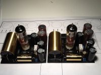
Just go asymmetrical with one tubestage and without the opamps. A Ecc99(6n6p) with 6k8 output resistor creates just 3x gain and the right harmonics. Using +/- 65v railvoltage for anodesupply and 12v for heater from the origenal power supply. See picture of my board.
Just go asymmetrical with one tubestage and without the opamps. A Ecc99(6n6p) with 6k8 output resistor creates just 3x gain and the right harmonics. Using +/- 65v railvoltage for anodesupply and 12v for heater from the origenal power supply. See picture of my board.
Attachments
I have to agree much better at low voltage than the ECC88. I've put in a 5687 as its the only spice model I trust. Works really well.

Last edited:
Yep R18 sets gain.
In the circuits in posts #70 and #71, what sets the gain for U4?
Last edited:
Imagine like its a simple op-amp with U4 and U3 the +/- inputs. The NF sets the gain so this is R18.
- Home
- Amplifiers
- Tubes / Valves
- Help with tube buffer