MJL21193 said:I removed the output inductor (and the resistor it's wrapped around) and replaced it with a short wire. This made a slight improvement to the ringing. No much though.
I added a 3.9pF cap (cheap disc ceramic) parallel to the feedback resistor (C14 in the old schematic). This made the ring much worse.
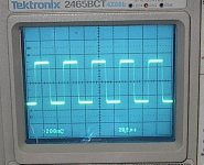
I reduced the capacitor to 1.2Uf by putting another in series with the first. The ringing was cut by more than half - it was barely noticeable at 1KHz and very much reduced in the 10K and 20K.
This ringing is obviously at 40K, as I have 2 ripples at 20K.
Using the .68F cap that I originally tried showed next to no ripple at any frequency.
John, I am glad to hear that the output inductor is not needed. ( I don't like them )
If it's 2 ripples at the top, and bottom it would be 80Khz, correct?
MJL21193 said:
Yeah, I'm not going to worry about a few watts. Besides, I'm not sure how accurately I'm measuring it. Hard to get it close to clipping with the top of your dummy load glowing red and tanning your face.
It would be nice to have a real function generator. Using the PC and my scopes calibrator sucks.🙂
If your meter has peak hold, you could put a 60hz sinewave into the amp and watch the scope until it clips and shut it off. The reading should be very accurate at that frequency.
Don S
Don S said:
If it's 2 ripples at the top, and bottom it would be 80Khz, correct?
If your meter has peak hold, you could put a 60hz sine wave into the amp and watch the scope until it clips and shut it off. The reading should be very accurate at that frequency.
Yes, my mistake, only looking at half the wave. 80K for sure. Better than the 1M is was.
I have a more accurate estimate of the output power - 96.5Vpp. About 145 watts into 8 ohms. This is very reasonable, I think.
Certainly I can live with it.
John, have you had a chance to listen to your amp without the output inductor. I am interested to see if you can hear a difference, and if there is, what it might be.
Don S
Don S
I have found that curing the ringing (not that due to the interaction of the load capacitance and the Thiele inductor) is not easy nor intuitive. The simple way is to increase the Cdom until the falling response reduces the gain and increases the gain and phase margins. But this simple way kills the sound quality. I have not yet acquired the skills of the true designer that can avoid this simple but plainly bad stabilisation method.Don S said:
Andrew, I don't follow you here, what are you stumped by?
This is where you lose me Andrew. With no PS droop your leach is 40W higher than the actual output.
Don S
The output Vp (=half Vpp) is well below the idle supply rail voltage for both the 8r0 and 4r0 cases. What bit don't you follow?
if the load resistor is that hot then what temperature have you driven the output device junctions to?MJL21193 said:Hard to get it close to clipping with the top of your dummy load glowing red and tanning your face.
It would be nice to have a real function generator. Using the PC and my scopes calibrator sucks.🙂
You are stressing the drivers and output devices severely using a reactive load. You must develop a method to get your readings in just a couple of seconds, otherwise you risk blowing up the amplifier due to exceeding the temperature de-rated SOAR.
Build a -20db switchable attenuator for the input signal. Flick the test signal up to see the scope display and flick it back down again to allow the amplifier and load to cool.
AndrewT said:I have found that curing the ringing (not that due to the interaction of the load capacitance and the Thiele inductor) is not easy nor intuitive. The simple way is to increase the Cdom until the falling response reduces the gain and increases the gain and phase margins. But this simple way kills the sound quality. I have not yet acquired the skills of the true designer that can avoid this simple but plainly bad stabilisation method.
Cdom is a simple way to create a dominent pole in an amp. I am sure there are many others. What is it that you don't like about Cdom comp, and what don't you like about it's sound
The output Vp (=half Vpp) is well below the idle supply rail voltage for both the 8r0 and 4r0 cases. What bit don't you follow?(132W seems quite low for a 2pair output stage)
How does the amount of outputs have to do with the PS, and circuit loss. Also why do you think John's is very low?
Don S
Don S said:John, have you had a chance to listen to your amp without the output inductor. I am interested to see if you can hear a difference, and if there is, what it might be.
Don S
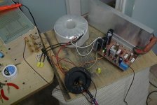
No, amp is still in it's highly professional test position (see pic).
What diference shoul ibe listening for?
Attachments
AndrewT said:I have found that curing the ringing (not that due to the interaction of the load capacitance and the Thiele inductor) is not easy nor intuitive. The simple way is to increase the Cdom until the falling response reduces the gain and increases the gain and phase margins. But this simple way kills the sound quality. I have not yet acquired the skills of the true designer that can avoid this simple but plainly bad stabilisation method.
Well, as I posted earlier, I have tested an actual speaker with this amp and those square wave shots showed no sign of ringing.
I'm not going to try to solve a problem that (to my way of thinking) is not a problem.
The load for this amp will most likely be the 2-way speakers as seen in one of my previous posts. This has a fairly complex passive filter and I could run the squarewave test on it to see what the results would be.
AndrewT said:
if the load resistor is that hot then what temperature have you driven the output device junctions to?
You are stressing the drivers and output devices severely using a reactive load.
Build a -20db switchable attenuator for the input signal. Flick the test signal up to see the scope display and flick it back down again to allow the amplifier and load to cool.
A bit of an exaggeration on my part. Load was hot, but not that hot. More the panic I feel when things heat up...
I'll build a switchable attenuator, like you suggest. Trick is when you want to get a snapshot of whats going on, and the resistors are sizzling while I try to hold the camera steady. 🙂
MJL21193 said:
The load for this amp will most likely be the 2-way speakers as seen in one of my previous posts. This has a fairly complex passive filter and I could run the squarewave test on it to see what the results would be.
And here it is. Squarewave at 20KHz into the speaker.
No ringing, no problem.
Attachments
Hi,
20kHz sqr into a speaker is maybe quite a benign test.
What are the impedances of the crossover and treble driver at frequencies from 20kHz to 200kHz?
try sweeping the frequency all the way down to 20Hz, but still keeping everything cool (not easy).
Half power into the crossover will probably blow the tweeter.
AndrewT said:Hi,
20kHz sqr into a speaker is maybe quite a benign test.
What are the impedances of the crossover and treble driver at frequencies from 20kHz to 200kHz?
try sweeping the frequency all the way down to 20Hz, but still keeping everything cool (not easy).
Half power into the crossover will probably blow the tweeter.
Did you mean 20khz for the tweeter, not 200khz?
Benign or not, this amp is made to drive speakers, not capacitors. I'll worry about driving electrostatics if I ever get them (doubtful).
The crossover is well made, final system test on Speaker Workshop shows the impedance to be fairly flat from (going from memory here) 100Hz up. Double hump in the impedance down low for TL alignment. Second order filter on the mid woofer, Zobel to reduce rising impedance on the mid woofer and a 2nd order filter plus pad on the tweeter.
I did sweep. When connected, the squarewave was at 1K. I went up and I went down. No sign of ringing anywhere.
I show the 20khz test because that's where the worst ringing was in the capacitor test.
I did mean 200kHz, I could have said 400kHz to include the even higher (odd) harmonics that are needed to make up the squarewave.MJL21193 said:
Did you mean 20khz for the tweeter, not 200khz?
I did sweep. When connected, the squarewave was at 1K. I went up and I went down. No sign of ringing anywhere.
I show the 20khz test because that's where the worst ringing was in the capacitor test.
The cap test is worst at high frequency because that is the lowest impedance presented by that reactive load.
A speaker has the worst case reactances anywhere and everywhere along the frequency range. But you have done a sweep and found none. Great you've checked. But are you going to do that check each time you change the cables or swap speakers or....
You're amp has turned out very well, it probably does not need any further stabilisation. But after you adjust some components to "voice" it to your ears/speakers/room, go back and check the final amp for stability.
Then enjoy your creation, well done!🙂
AndrewT said:
But are you going to do that check each time you change the cables or swap speakers or....
You're amp has turned out very well, it probably does not need any further stabilisation. But after you adjust some components to "voice" it to your ears/speakers/room, go back and check the final amp for stability.
Then enjoy your creation, well done!🙂
Thanks Andrew,
The cable I used for that test was roughly 20 feet of zip cord, as I don't have room to put that speaker in my "lab", it was in the next room.
I have not finished tinkering with it. I will re-establish the 2 pole compensation today to see if this reduces the ringing.
As for voicing, I like what I hear so far. There are a few components that need to be switched, such as the places on the schematic where there is a 1uF cap indicated, I have used a .47uF (all I presently have).
Also there is the cascode bias. I've changed it to the 2 LEDs, but would like to try the 5V zener. Do you think that this would make a difference?
Hi,
did you ever get around to measuring the LED voltage for me?
Raising the cascode voltage to 5V may reduce the input capacitance, but whether this would be audible or measurable is open for now.
did you ever get around to measuring the LED voltage for me?
Raising the cascode voltage to 5V may reduce the input capacitance, but whether this would be audible or measurable is open for now.
AndrewT said:Hi,
did you ever get around to measuring the LED voltage for me?
Raising the cascode voltage to 5V may reduce the input capacitance, but whether this would be audible or measurable is open for now.
The LEDs are 1.8V, so I'm getting ~3.6V from the pair.
I'm also going to bump up the differential stage current a bit (running 1.8mA right now). I reduced this when I switched the BC550s for the LM394
The waveform in this post had me seriously concerned about stability. I would not expect the change that you saw removing the feedback cap, and it does not show the change in simulation which should be accurate, does not make sense. I have to wonder if there is an error in your build, I'll check if you post the schematic and artwork:
http://www.diyaudio.com/forums/showthread.php?postid=1384133#post1384133
Could you be taking the feedback after the output inductor?
It looks enough good now, as long as you're not driving ES speakers or insane cables. Good that you did the test anyway.
I'd experiment with pole zero compensation, which involves putting a 50-100 resistor in series with the Cdom cap, if you want to improve the stability into capacitive loads. Fewer parts to play with than with TMC.
Lowering the diff pair bias, lowers the dominant pole, so if you raise it Cdom should be increased to compensate and preserve stability.
Pete B.
PB2 said:
I would not expect the change that you saw removing the feedback cap,
Could you be taking the feedback after the output inductor?
I'd experiment with pole zero compensation, which involves putting a 50-100 resistor in series with the Cdom cap, if you want to improve the stability into capacitive loads. Fewer parts to play with than with TMC.
Lowering the diff pair bias, lowers the dominant pole, so if you raise it Cdom should be increased to compensate and preserve stability.
Hi Pete,
Removing that feedback cap solved the problem completely. I tried a lower one yesterday (3.9pF) during the capacitive load test. It made no difference.
The feedback on that board is coming from the centre of the output trace that goes across the board. I have since changed that to the end of that trace (closer to the speaker output.
I have just raised the input current from 1.8mA to 2.6mA and changed the single pole compensation back to 2 pole compensation. I tried the capacitor test again with no improvement in the outcome. In fact, the 2-pole compensation added a slight leading edge overshoot to the squarewave.
I am not sure about the resistor value I'm using for this compensation. I have located a paper
here but I haven't had the time to read it over 20-30 times so that I might understand it. 🙂
I will give 0-pole a try.
I just ran a new batch of tests with RMAA with the amp running the new changes. I'll post those next.
Here are the test results.
The first test is the the sound card test. I'm not sure why it's reading THD as .0041% now, when it was .002% before.
First amp test is at idle current 60mA (16 is for the 16mVdc across the emitter resistor).
The next is at 96mA and the last is at 133mA.
The tests were run at about 70 watts output into my 4.4 ohm dummy load.
I'm going to assume that the distortion numbers of the device being tested are the results minus the sound card numbers. If that is the case, even if the sound cards distortion is .002% as in the first tests, that means the amps distortion at 70 watts is .0031% to .0038%.
Still, I see better results from the previous run of tests and that was at 100 watts into load. What to blame? Raising the input current or the 2-pole compensation? Or both?
Attachments
MJL21193 said:
Still, I see better results from the previous run of tests and that was at 100 watts into load. What to blame? Raising the input current or the 2-pole compensation? Or both?
Even though I haven't ran anymore tests, I returned to the single pole compensation (after trying the pole 0 recommended by Pete - it didn't make any difference).
Better to keep things as simple as possible, if it works well, why fix it?
I left the input current at 2.6mA. Increasing this didn't make any appreciable difference.
Experimenting with the Vbe multiplier and have changed the 1K value of one resistor to 900 ohms (makes for smoother adjustment).
I checked proper operation of the Vbe by running the amp until the heat sink was well heated up. I then took my heatgun and made the heatsink too hot to comfortably touch. The voltage across the emitter resistors stayed constant (+/-2-3mV). That's good.
I did some more tinkering, but performance was not improved. The output inductor that was removed earlier was replaced. Close examination of the squarewave on 10X magnification shows a subtle improvement with it in.
A schematic update soon, and also a new board layout.
Since this is not a commercial circuit to worry further for its bullet proof status, and you can't possibly check it on electrostatics etc. plus it sounds good, I guess that you are ok to go make a stereo one and listen for pleasure. If some other DIYer makes it in the future and finds problems in other system situations, I guess that this thread will happily try to patch it further. Happy new year from me and happy listening! I am quite impressed by your bold take in creating your very own amp and having proceeded so long. Bravo.
- Status
- Not open for further replies.
- Home
- Amplifiers
- Solid State
- Help with this amp? A patchwork product of simulation