I just finished some high power tests with RMAA. I had to add another 1.5K is series with my voltage divider in order to get the voltage down enough for the sound card.
The input to the amp was 2.1 Vpp (.740Vrms). I had to use the dummy load for the testing. The speaker was way too loud and I don't think it could handle that much power (it's only rated 30 watts).
I measured the resistance of the dummy load when hot and it's 4.4 ohms. That gives ~108 watts into the load ( output= ~70Vpp).
Idle current was set to about 95mA and the heatsink was nicely warmed up.
Here are the results. The first test is the sound card. The next two are the amp at 95mA idle and the last test is with the idle turned down to ~75mA.
Attachments

PB2 said:
Note that Marshal Leach tests with a 2uF load, you might want to consider this with regard to stability:
http://users.ece.gatech.edu/~mleach/lowtim/bckgrnd.html
Hi Pete,
I've read What Leach has to say about capacitive testing, but it lacks details on how to do it. Is it just the speaker output connected to a single capacitor with no other load?
What about voltage rating? What output level should this test be run at?
I have a Solen 2.2uF, 400V - would this do the trick?
start with 47nF//8r0. using a range of output voltages 1Vac to 30Vac.
then increment the cap from 47nF to 2uF, again testing at a variety of voltages.
Finally, try 4r0//cap for all of those combinations.
Look at both square wave and sinewave test signals.
Use a -20db signal switch to expose the amp to less stress during each test run.
then increment the cap from 47nF to 2uF, again testing at a variety of voltages.
Finally, try 4r0//cap for all of those combinations.
Look at both square wave and sinewave test signals.
Use a -20db signal switch to expose the amp to less stress during each test run.
Thanks Andrew,
I'll give it a try.
What are the possible fixes if it proves to be unstable with the capacitor?
How should I interprete the results from RMAA? Should I take the sound cards measured distortion and subtract that figure from the measurements made through the amp?
I'll give it a try.
What are the possible fixes if it proves to be unstable with the capacitor?
How should I interprete the results from RMAA? Should I take the sound cards measured distortion and subtract that figure from the measurements made through the amp?
MJL21193 said:
How should I interprete the results from RMAA? Should I take the sound cards measured distortion and subtract that figure from the measurements made through the amp?
AndrewT said:no.
use an analogue scope to look for oscillation in part of the output waveform or for excessive peaking of the leading edge of the squarewave.
Sorry, that was a different subject. I'm refering to the results from the RMAA tests that are posted above, not how to check for oscillation (I already know how to do that).
AndrewT said:start with 47nF//8r0. using a range of output voltages 1Vac to 30Vac.
then increment the cap from 47nF to 2uF, again testing at a variety of voltages.
Finally, try 4r0//cap for all of those combinations.
Look at both square wave and sinewave test signals.
Use a -20db signal switch to expose the amp to less stress during each test run.
I tried it. I started with a .68 mylar parallel to my 4.4 ohm dummy load. No sign of instability, all the way up to about 80Vpp.
I then skipped anything else and used a Solen 2.4uF / 250V speaker cap in parallel with the dummy load.
No sign of instability at all. I drove this to near full output power too.
I am trying to determine the peak output power of the actual amp. Simulation shows it to be to produce 160 watts before clipping. That's about 102Vpp.
Testing with the PC funtion generator shows the maximum voltage swing before clipping is ~92Vpp. This winds up being about 132 watts into 8 ohms.
Where could I be losing that extra 10 volts?
Testing with the PC funtion generator shows the maximum voltage swing before clipping is ~92Vpp. This winds up being about 132 watts into 8 ohms.
Where could I be losing that extra 10 volts?
John, what load were you using for this test? What is the power supply voltage at when the amp is loaded and driven to clipping? Did your sims include power supply droop under load?
Don S
Don S
Don S said:John, what load were you using for this test? What is the power supply voltage at when the amp is loaded and driven to clipping? Did your sims include power supply droop under load?
Don S
Hi Don,
The load is my 4.4 ohm dummy load. I measured the supply voltage at idle - 111.2Vdc. At ~60Vpp output into the dummy load, I measured 105.6 across the rails. So a bit of a drop.
The sim doesn't allow for droop, and I failed to account for it. Thanks for pointing that out.
From the link Pete posted above, with regard to the Leach amp:
"
With power supply voltages of about 58 V dc (+ and -), the amplifier will put out an average sine wave power of 120 watts per channel with an 8 ohm load. "
I'm probably ok at ~132 watts. I measured output swing with the scope on the 1V scale with the prode on 10X. Might be a bit of error there as my Extech "true RMS" meter says 34.34Vrms (would be 147 watts/8 ohms).
Not that big of a deal anyway.
I ran the capacitive load test with the sine wave output from the RTA tone generator on the PC. The square wave output is not clean enough from either this program or the other tone generator I have there - one from NCT.
The sine wave output, once the capacitor was connected, showed no difference at all.
I just re-ran those tests using the clean squarewave output from the scopes calibrator. There is some ringing. This is as detailed above, with the 2.4uF in parallel with the 4.4 ohm load.
Here's how it looks at 1Khz:
Attachments
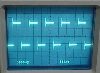
John, my best estimate is that it is ringing at about 100Khz. I wonder if this an interaction with your output inductor and the capacitive load? It would be interesting to see if it sims the same way.
Don S
Don S
John, It would also be interesting to see how the amp operates without the output inductor circuit. Both in sim and reality.
Don S
Don S
Hi,
that's where I get stumped. I can identify the ringing even when the test square goes through the input RF filter, but getting a reasonably shaped square is difficult without massively increasing the value of the Cdom cap and that kills the sound.
Yes, low impedance and parallel capacitance (=real speaker over narrow frequency range) is a demanding load.
How low does the C need to be for the ripple to disappear?
How low does the C need to be to eliminate the peaking of the squarewave?
BTW,
keep these test signals of very short duration. They dissipate a lot of energy in the outputs and quickly raise the temperature of the heatsinks, including the drivers'. I do a scope view first (about 1second) to check for no clipping, pause (-20db switch) for a short cool down period and then a short test, just long enough to get a stable reading on the bench DMM (about 1.5 to 2seconds).
I got 171W (37Vac, ~104.6Vpp) into 8r0 from +-58Vdc (40Vac transformer) at idle and 311W (35.3Vac, ~99.8Vpp) into 4r0 using a 3pair Leach clone. Note that the Vac drops by 1.7V (-0.4db) changing from 8r0 to 4r0.
132W seems quite low for a 2pair output stage. But scaling from 4r4 to 8r0 is not a fair assessment.
Don S said:John, my best estimate is that it is ringing at about 100Khz. I wonder if this an interaction with your output inductor and the capacitive load? It would be interesting to see if it sims the same way.
Don S
The simulator is not really good for this kind of thing, but a slight ringing is evident. Removing the output inductor in the sim tamed this.
Is there a cause for concern though? This ringing is not full blown oscillation, and this is a very tough load to drive.
I will see if the situation improves without the inductor in the amp.
Don S said:John, It would also be interesting to see how the amp operates without the output inductor circuit. Both in sim and reality.
Don S
AndrewT said:
I got 171W (37Vac, ~104.6Vpp) into 8r0 from +-58Vdc (40Vac transformer) at idle and 311W (35.3Vac, ~99.8Vpp) into 4r0 using a 3pair Leach clone. Note that the Vac drops by 1.7V (-0.4db) changing from 8r0 to 4r0.
132W seems quite low for a 2pair output stage. But scaling from 4r4 to 8r0 is not a fair assessment.
I have some resistors on order to construct an 8 ohm dummy load.
Do you have any suggestions as to where I could be dropping voltage?
AndrewT said:Hi,
that's where I get stumped. I can identify the ringing even when the test square goes through the input RF filter, but getting a reasonably shaped square is difficult without massively increasing the value of the Cdom cap and that kills the sound.
Andrew, I don't follow you here, what are you stumped by?
Yes, low impedance and parallel capacitance (=real speaker over narrow frequency range) is a demanding load.
How low does the C need to be for the ripple to disappear?
How low does the C need to be to eliminate the peaking of the squarewave?
BTW,
keep these test signals of very short duration. They dissipate a lot of energy in the outputs and quickly raise the temperature of the heatsinks, including the drivers'. I do a scope view first (about 1second) to check for no clipping, pause (-20db switch) for a short cool down period and then a short test, just long enough to get a stable reading on the bench DMM (about 1.5 to 2seconds).
I got 171W (37Vac, ~104.6Vpp) into 8r0 from +-58Vdc (40Vac transformer) at idle and 311W (35.3Vac, ~99.8Vpp) into 4r0 using a 3pair Leach clone. Note that the Vac drops by 1.7V (-0.4db) changing from 8r0 to 4r0.
132W seems quite low for a 2pair output stage. But scaling from 4r4 to 8r0 is not a fair assessment.
This is where you lose me Andrew. With no PS droop your leach is 40W higher than the actual output.
Don S
MJL21193 said:
I have some resistors on order to construct an 8 ohm dummy load.
Do you have any suggestions as to where I could be dropping voltage?
John, BJT's drop about 0.7V at every junction, the output emitter resistors drop the output also, as does the internal resistance of the device. There are lots of places for loss (many of the resistors in the circuit). Every lost volt P2P will drop your RMS output by a factor of 2.83 : 1
Don S
I removed the output inductor (and the resistor it's wrapped around) and replaced it with a short wire. This made a slight improvement to the ringing. No much though.
I added a 3.9pF cap (cheap disc ceramic) parallel to the feedback resistor (C14 in the old schematic). This made the ring much worse.
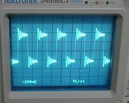
I reduced the capacitor to 1.2Uf by putting another in series with the first. The ringing was cut by more than half - it was barely noticeable at 1KHz and very much reduced in the 10K and 20K.
This ringing is obviously at 40K, as I have 2 ripples at 20K.
Using the .68F cap that I originally tried showed next to no ripple at any frequency.
I added a 3.9pF cap (cheap disc ceramic) parallel to the feedback resistor (C14 in the old schematic). This made the ring much worse.
I reduced the capacitor to 1.2Uf by putting another in series with the first. The ringing was cut by more than half - it was barely noticeable at 1KHz and very much reduced in the 10K and 20K.
This ringing is obviously at 40K, as I have 2 ripples at 20K.
Using the .68F cap that I originally tried showed next to no ripple at any frequency.
Don S said:
John, BJT's drop about 0.7V at every junction, the output emitter resistors drop the output also, as does the internal resistance of the device. There are lots of places for loss (many of the resistors in the circuit). Every lost volt P2P will drop your RMS output by a factor of 2.83 : 1
Don S
Yeah, I'm not going to worry about a few watts. Besides, I'm not sure how accurately I'm measuring it. Hard to get it close to clipping with the top of your dummy load glowing red and tanning your face.
It would be nice to have a real function generator. Using the PC and my scopes calibrator sucks.🙂
- Status
- Not open for further replies.
- Home
- Amplifiers
- Solid State
- Help with this amp? A patchwork product of simulation