Hi,
with that hole you have options.
You can bolt the To126/220 package to top side or bottom side.
On topside an insulating spacer and a small heatsink under the package for To220, or heatsink on top for a reversed To126.
In any case, a similar hole for every medium power device is very useful.
with that hole you have options.
You can bolt the To126/220 package to top side or bottom side.
On topside an insulating spacer and a small heatsink under the package for To220, or heatsink on top for a reversed To126.
In any case, a similar hole for every medium power device is very useful.
AndrewT said:Hi,
with that hole you have options.
Hi,
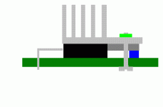
I have it for heatsink to sit on top, facing up. That way I don't need to change the pin routing and worry about side clearance for the sink.
I saw the space there, so might as well use it up.
EDIT: Andrew, do you think the 2 ounce copper on the top would provide enough cooling for this VAS without a heat sink?
I wouldn't use the PCB for cooling. It might short out.
What is your estimate for the PCB dissipation? 100C/W or 1kC/W?
But you like to run big currents and that probably needs a real sink. 20C/W does not take much space.
What is your estimate for the PCB dissipation? 100C/W or 1kC/W?
But you like to run big currents and that probably needs a real sink. 20C/W does not take much space.
AndrewT said:I wouldn't use the PCB for cooling. It might short out.
What is your estimate for the PCB dissipation? 100C/W or 1kC/W?
But you like to run big currents and that probably needs a real sink. 20C/W does not take much space.
The clip on types are between 22 and 20K/w and pretty small, you may even use a piece of 1.0 mm aluminium sheet, about 15 x 25 mm will do.
Nico Ras said:
Or speaker designers just lost the nack for making efficient descent sounding speakers.
You like that?
To the contrary.
John, have you done any more testing for specifications? What is the actual -3DB points of the amp. Have you made distortion tests with the PC sound card?
Don S
Don S
Don S said:John, have you done any more testing for specifications? What is the actual -3DB points of the amp. Have you made distortion tests with the PC sound card?
Don S
Hi Don,
I went out today and bought a new sound card and I've just finished installing it. I am now checking over my Wallen jig, which will save me from destroying this sound card (like I did with the last one).
As soon as I get everything hooked up and running right, I'll try to get a measurement with RMAA.
Judging from the squarewave response and my own listening impressions, I'll be very surprised if the distortion number is a nasty one.
BTW, what's the -3db points?
John, while I believe that too much distortion is a bad thing, that in itself is not the whole story of an amp.
Every amp will have a HF rolloff, generally specified as the 3DB down point (-3DB@), 70Khz, 100Khz, 200Khz. Well you get the idea.
If the amp will not amplify DC, then it will have a LF rolloff. In your design C7 and C13 both provide LF rolloff. 6DB per octave for each capacitor, or filter if you like. C7 prevents DC and LF from getting in and amplified and C13 in the feedback circuit provides 100% feedback of all DC in the circuit's amplification, and can be crucial to good DC offset. You will have a LF rolloff at some frequency of 12DB/Octave, 6DB for each cap or filter. This is what causes your squarewaves to start tilting as frequency is decreased.
Don S
Don S said:John, while I believe that too much distortion is a bad thing, that in itself is not the whole story of an amp.
Every amp will have a HF rolloff, generally specified as the 3DB down point (-3DB@), 70Khz, 100Khz, 200Khz. Well you get the idea.
Hi Don,
I thought that's what you meant, but I assumed it was predetermined by those filters.
Well, I have results from the RMAA. It took a while to get everything set up. I was going to us my Wallin jig first, but reconsidered. I thought it would put the output impedance too high. In the end, I made a voltage divider, using several 1/4 watt resistors in parallel for 1K and 100R.
I spent a lot of time checking and rechecking the output before I connected to the new sound card. Finally got things right and ran two tests.
Here are the results:
Attachments
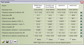
John, nice distortion numbers. I saw frequency response but no frequency limits for the numbers. Also what was the amplifier load and power output at when you tested?
Don S
Don S
You might want to have a look at the slew rate by finding the frequency where the output becomes triangular in shape at high signal levels for both positive and negative going waveforms. Might only want to do this in simulation to avoid putting large signal HF into the amp which can blow it up. Here are some notes about slew rate:
http://www.ece.vt.edu/ece3254/Prelab_notes/Pre8_intro.pdf
SR = 4Af
where:
f is the frequency where the output becomes triangular.
A is the peak amplitude of the triangular waveform.
Pete B.
http://www.ece.vt.edu/ece3254/Prelab_notes/Pre8_intro.pdf
SR = 4Af
where:
f is the frequency where the output becomes triangular.
A is the peak amplitude of the triangular waveform.
Pete B.
A paper covering feedback, note Figures 27-32:
http://web.mit.edu/klund/www/papers/ACC04_opcomp.pdf
Pete B.
http://web.mit.edu/klund/www/papers/ACC04_opcomp.pdf
Pete B.
Don S said:John, nice distortion numbers. I saw frequency response but no frequency limits for the numbers. Also what was the amplifier load and power output at when you tested?
Don S
Load is a 4 ohm dummy. Power output was low. I will run more tests later at higher output power (a little nervous about burning up this new card).
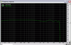
Here's the frequency response graph for the 4th test. It matches the sound cards response almost perfectly.
Attachments
PB2 said:You might want to have a look at the slew rate by finding the frequency where the output becomes triangular in shape at high signal levels for both positive and negative going waveforms. Might only want to do this in simulation to avoid putting large signal HF into the amp which can blow it up.
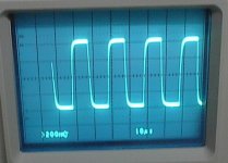
Hi Pete,
I did a very brief test at 40KHz back when I did the the 20KHz into athe dummy load. This was at the 200mVpp output from the calibrator.
Here it is:
Attachments
MJL21193 said:
Hi Pete,
I did a very brief test at 40KHz back when I did the the 20KHz into athe dummy load. This was at the 200mVpp output from the calibrator.
Here it is:
You have to drive it to a large signal level, say +/- 30-40 V peak, however, probably not a good thing to do in real hardware.
Small signal is not a true test.
Pete B.
PB2 said:
Small signal is not a true test.
How about those distortion numbers? And the excellent square wave response? What about the actual listening?
How about the fact that it's 100% stable?
Those are the tests that count in my book.
Sorry Pete, but would it kill you to say "well done"?
So, what you're really doing is fishing for a pat on the back. I don't think there's much more to say here. Enjoy the journey John!
Pete B.
Pete B.
So, what you're really doing is fishing for a pat on the back. I don't think there's much more to say here. Enjoy the journey John!
Note that Marshal Leach tests with a 2uF load, you might want to consider this with regard to stability:
http://users.ece.gatech.edu/~mleach/lowtim/bckgrnd.html
It's probably about time I just go work on my own design.
Pete B.
Note that Marshal Leach tests with a 2uF load, you might want to consider this with regard to stability:
http://users.ece.gatech.edu/~mleach/lowtim/bckgrnd.html
It's probably about time I just go work on my own design.
Pete B.
PB2 said:So, what you're really doing is fishing for a pat on the back. I don't think there's much more to say here. Enjoy the journey John!
Pete B.
Yes, a pat on the back would be ok once in a while. Everyone likes one.
It's like I've said before Pete, this wouldn't be the amp it is without your input. And I still need it.
The good results have pumped me up, swelled my head. I'll need to get over that.
Sorry if I was a little short with you earlier. 🙂
- Status
- Not open for further replies.
- Home
- Amplifiers
- Solid State
- Help with this amp? A patchwork product of simulation