Nico Ras said:
ITS LIKE COOKING WITH GAS!!!!!
Well, when you get over the euphoria that the darn even turns on and works, it's time to work out the bugs, right? Too many measurements with a live high power amp board is bound to have some mishaps. I accidentally shorted heatsink angle bracket to negative rail voltage - burned a hole nearly clean through the board! Blunted my probe tip too.
salas said:Its always a bit surprising from sim to bench. Typical stuff. I only patch the feedback after I see the finished real layout performance on the scope... I saw your thread only today. I see you use 30dB gain. What is the 8 Ohm power? How much is your feedback? Are you about to listen with those nicely curved 3ways with passive cross or you are building 6 channels to go straight to active?
The 8 ohm power is 160 watts.
This amp will be for another set of speakers, bigger than the active pair (which are driven by 6 active amps, LM3886's).
At one point, I was actually tempted to use 6 of these amps for that set, as the chip amp project wasn't going so well.
Passive Xover? Never again. I have seen (or rather heard) the light, and that's active.
Hi John,
First, I strongly suggest, since you're having stability problems, that you remove R38. Indeed, it should not be used if you do not also bootstrap the cascode.
Next, it would certainly be worth it to find a tutorial covering the basics for simple feedback amplifier stability and Cdom compensation. The dominant pole is set, mainly, by the diff pair bias current, the value of the Cdom cap, and the gain of the Vas. Altering the diff pair bias current is moving the dominant pole which is fundamental to stability. You could simply make Cdom larger and probably end up with the same if not better result. Also, altering the Vas current is moving on both the beta and Ft curves, so it is not the bias alone at work here. You are starving the Vas and drivers in my opinion. You are probably slowing down the output stage, when what you really need to do is increase the Cdom, or lower the dominant pole, and keep the OS reasonably fast. The OS is also sensitive to load, obviously.
Stability is no simple matter and I was hoping that a large Cdom cap would make it easy for you. In fact, it is the first thing to try, even if your goal is to use a smaller one in the end.
The ringing is asymmetric because the output stage is strongly driven (faster) on the Vas side, and not as fast on the bootstrap side, the loop bandwidth is different for positive and negative going waveforms. The solution is to raise the bias (stronger drive from the bootstrap, and make Cdom larger to provide the dominant pole. You might also want to bypass the 100uF with a stacked .1uF to improve the HF performance. You want to get the positive and negative sides closer.
It is important to also test with capacitive loads.
If altering the Cdom does not alter the freq of oscillation, then it is more likely local to the output stage. You might be chasing the wrong problem when it is actually local to the ouput stage. You might need to further decouple the load with a larger output inductor, and larger parallel resistor if you do not do careful stability analysis to verify that the smaller value is safe.
Pete B.
I spent some time earlier actually listening to this amp, connected to a good speaker. I think it's there in every way. It has speed, power and bandwidth to spare.
Clean, crisp, clear treble - very accurate.
Effortless bass, tight, authoritative.
Everything in between is sweat, smooth.
I judge it better than the GCs I've built by a wide margin and there is no contest between it and my Yamaha HTR.
Latest and hopefully the last schematic update.
I have made a few changes, to mirror the very successful present configuration of the fully operation, most excellent Patchwork amplifier!
Not only have I removed C14 from the board, but I have brought it out to my shop and crushed it's uselessness into silver-mica dust.
I have decided to use two LEDs in place of the zener. It works so well, why change it? Sim says it's all good.
Kept the Vbe multi the same, as it works fine.
Reduced R18 to 220 ohms. This allows enough current to flow through the drivers. Noticed before, on the prototype the original value was 100R - this got so hot during operation, it turned brown.
Maintaining about 6.9mA through the VAS. This transistor reached a peak temperature of 68 degrees in the prototype. Too hot! It doesn't need to run that much current.
I measured DC offset at 5.6mV with no signal. I hear no hiss or hum from the speaker. There is no thump (at all, NONE) when I turn it on (by plugging it into the power bar).
There is no thump or other strange sound when power is cut, it just keeps playing for a few seconds till the caps drain.
Happy, am I. Can you tell? 🙂
Attachments
PB2 said:
First, I strongly suggest, since you're having stability problems, that you remove R38. Indeed, it should not be used if you do not also bootstrap the cascode.
Pete! You're back!
Merry Christmas and happy new year.
You've missed some exciting stuff. Please look at pic of square wave output in post#476. No more instability!
Sorry to say you're dead wrong about the bootstrap on the differential pair. It makes a big difference. This is one of the things I looked at when I was taking a hatchet to the circuit. Without that resistor, distortion increases.
Now, this is not something that I can hear, but the sim says leave it in. It's good for about a .004% decrease in distortion at 20KHz.
Merry Christmas, happy new year to all!
Well, John you can ignore my input that's fine, you debug by
pulling parts, so good luck to you. I don't think removing that
cap is a good indication that all is well, it will probably oscillate someday when you least expect it.
Good luck to you!
Pete B.
Well, John you can ignore my input that's fine, you debug by
pulling parts, so good luck to you. I don't think removing that
cap is a good indication that all is well, it will probably oscillate someday when you least expect it.
Good luck to you!
Pete B.
PB2 said:
Well, John you can ignore my input that's fine, you debug by
pulling parts, so good luck to you.
Hi Pete,
I'm not ignoring your input. The amp wouldn't be where it is now without your input.
I have to go with what works. If that means removing parts or even whole circuit sections, that's what I'll do. The proof of the performance shows in the sim and in the real world. That's a 20khz squarewave in post #476, on a real scope in real time.
My understanding is limited, but I'm learning. I believe C14 paralleled with the feedback resistor forms a type of filter, yes? I also see that not every amp design includes this cap, among those would be the source for a good part of this amp - Doug Self's Blameless. Is it a bad thing to eliminate something that is not needed and indeed, instead of enhancing performance, diminishes it?
Pete you've been a real friend through all of this. Your contribution in support alone is worth more to me than I can say.
Thanks.
Hi,
that FB cap was the same problem in the Symasym.
22pF with MJL and only 3.3pF with 2sa, both 30MHz types.
It might be worth reading through Pavel's site to understand what he did to solve his problem.
http://www.lf-pro.net/mbittner/Sym5_Webpage/symasym5_3.html
that FB cap was the same problem in the Symasym.
22pF with MJL and only 3.3pF with 2sa, both 30MHz types.
It might be worth reading through Pavel's site to understand what he did to solve his problem.
http://www.lf-pro.net/mbittner/Sym5_Webpage/symasym5_3.html
AndrewT said:Hi,
that FB cap was the same problem in the Symasym.
22pF with MJL and only 3.3pF with 2sa, both 30MHz types.
It might be worth reading through Pavel's site to understand what he did to solve his problem.
http://www.lf-pro.net/mbittner/Sym5_Webpage/symasym5_3.html
Thanks Andrew. Reading that, it sounds exactly like my problem and the steps Pavel took to solve it are nearly identical to what I did.
As for C14, I'm not tempted to put any value back there, as I can not see the value in doing so.
Overall Andrew, what do you think? You have been following this thread from the start - does it look like a reasonable amp now? Do the voltages and currents throughout look accurate?
I will run some more test today, maybe go out and get a new sound card for that computer. It would be a PITA to drag everything up here for testing on this computer, and knowing my track record, I'd need a new sound card for this one too by the end of the day.😉
Hi,
most of what you are left with I can understand. Some of the earlier complexity lost me.
This lead, lag, forward, backward compensation is still a mystery to me, but those who know how to use/balance it, seem able to get stability for a wider range of reactive loads.
Does that equate to the same amplifier sound with different cables/speakers? Or in other words, get it sounding right and then it won't change with changes in loading.
Drivers and/or VAS too hot, then fit bigger sinks!! Don't reduce your currents.
AndrewT said:
Drivers and/or VAS too hot, then fit bigger sinks!! Don't reduce your currents.
In it's current configuration, do you think the VAS and drivers are getting enough current?
It's not a big deal to change these. Is it necessary though?
At idle (idle current 70mA) the VAS has 6.8mA and the drivers have 6mA.
Changing bootstrap resistors 35 and 40 to 3.3K and R18 to 100R gives Vas=8.3 and drivers=12.7
Hi,
I would try the VAS @ 8mA and the drivers at 20mA or even 30mA.
The output stage @ 70mA total, or 70mA each device?
70mA * 0r27=19mV (in the range 15mV to 25mV).
Try C1 & C16 @ 1mF. If it does not sound good then return to 100uF.
What is the voltage on the cascode LEDs?
I would try the VAS @ 8mA and the drivers at 20mA or even 30mA.
The output stage @ 70mA total, or 70mA each device?
70mA * 0r27=19mV (in the range 15mV to 25mV).
Try C1 & C16 @ 1mF. If it does not sound good then return to 100uF.
What is the voltage on the cascode LEDs?
AndrewT said:Hi,
I would try the VAS @ 8mA and the drivers at 20mA or even 30mA.
The output stage @ 70mA total, or 70mA each device?
70mA * 0r27=19mV (in the range 15mV to 25mV).
Try C1 & C16 @ 1mF. If it does not sound good then return to 100uF.
I'll try it out, see if it's still stable (no way it would be with C14 before).
That's ~70 per device, not total. About 20mV across the emitter resistors.
I don't have any 1000uF caps with a 63V (or higher) rating, so I can't try that. On the one I'm using now I have used 330uF instead of 220Uf for C5 and C18.
I just have to show that square wave again.

Attachments
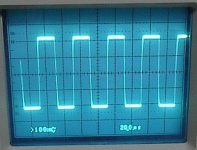
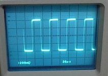
I changed the bootstrap resistors to put more current through the VAS and reduced R18 down to 55 ohms (I put 3 other 220R is parallel). Attach the amp to my 4 ohm dummy load (4-1 ohm, 25 watt resistors in series).
Turned on and adjusted idle current. Check for oscillation - none.
I input the squarewave from the scope. Look for oscillation again: still none.
This is a shot of the amp running the higher currents with a 20KHz squarewave:
Turned on and adjusted idle current. Check for oscillation - none.
I input the squarewave from the scope. Look for oscillation again: still none.
This is a shot of the amp running the higher currents with a 20KHz squarewave:
Attachments
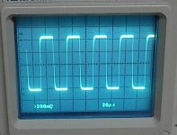

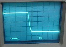
I have ran the same squarewave with the amp connected to my test speaker. This is a 4 ohm coax (2-way) car speaker with an Re of 3.2 ohms.
Luckily, I can't hear 20KHz and I'm not sure if the tweeter on this Pioneer speaker can actually reproduce that frequency. I can hear 5K and 10K, and I tested there briefly to see how things look. I still have ringing in my ears.🙂
Anyhow, here's how it looks. 20KHz squarewave input.
BTW, absolutely no sign of instability at all.
Attachments
I have spent most of the day and part of tonight listening to this amp. Sounds mighty fine.
I took the time to replace all of the resistors that I had temporarily tacked on, in order to get it running right. I made a new heat sink for the VAS and put that on, and epoxied it to the board.
I then turned it on and it was on all day, right up to about an hour ago. Most of the time playing music, but I left it for a couple of long stretches just idling. The angle bracket seems to work well for transferring the heat to the heat sink (I have a big one from BarredBoss on Ebay that I've clamped to the angle).
The heat sink was fairly warm after a couple of CDs played at high volume, though I was not coming anywhere near the 160 watts this amp is capable of. More like 25 watts at the most.
It ran stable all day long, with no change in behavior at all. A few times I checked idle current and saw no major change there either.
Yet another schematic update. I'm not even going to bother saying it's the final one.
I will also make the changes to the board layout, and I'll post that when it's done.
Attachments
New board layout.
I have removed the deleted components, changes a few things around and changed R17 pot to a Bourns 3296W.
I moved the negative rail away from the output trace a bit. It was not the source of problems, but better to have a little more clearance there anyway.
I re-sized the speaker output terminal block and moved some parts around, as there wasn't enough room for it before.
Copper top layer will be as before, with the single slot across the board.
Attachments
- Status
- Not open for further replies.
- Home
- Amplifiers
- Solid State
- Help with this amp? A patchwork product of simulation