MJL21193 said:Hi Nico,
The magnified scale is 2.1uS. When I say 1MHz, that's really a ballpark figure. I'd like to know if it's possible that this is the result of parasitic inductance/capacitance between the output trace and the negative rail.
Here's a shot of the top half of the wave magnified 10X. No ringing.
Its bcs you use your 1MHz calibration on board scope gen? I see almost half a scale of your negative square ringing in your 21μs setting pic, so it must be a 100kHz problem?
MJL21193 said:Hi Nico,
The magnified scale is 2.1uS. When I say 1MHz, that's really a ballpark figure. I'd like to know if it's possible that this is the result of parasitic inductance/capacitance between the output trace and the negative rail.
Here's a shot of the top half of the wave magnified 10X. No ringing.
John this could very well be the probe, it is probably 10 Meg at 1 or more PF, you are feeding it with a very low impedance. Try using simple wire and crocodile jaws in stead of the probe.
John also try a sine wave at high output, if you see ripple in the rising or falling this is oscillation in the amp. If you do not have a sine wave generator, use your PC card. I will email you a generator. It is pretty good for general purpose jobs.
salas said:
Its bcs you use your 1MHz calibration on board scope gen? I see almost half a scale of your negative square ringing in your 21¼s setting pic, so it must be a 100kHz problem?
Hi Salas,
The calibrator is variable. The oscillation is posted back in post#432. This is at 247nS/div giving ~500nS for the wave. That's close to 1MHz.
Nico Ras said:
John this could very well be the probe, it is probably 10 Meg at 1 or more PF, you are feeding it with a very low impedance. Try using simple wire and crocodile jaws in stead of the probe.
The input impedance to the amp is 500K (R15, across the input). Probe reads a clean squarewave though the connecting cable, not connected to the amp.
Nico Ras said:John also try a sine wave at high output, if you see ripple in the rising or falling this is oscillation in the amp. If you do not have a sine wave generator, use your PC card. I will email you a generator. It is pretty good for general purpose jobs.
No sound card (see above)!! I'll need to go out tomorrow and pick one up.
Thanks Nico, but I already have a PC function generator.
Yes, now I went back and saw what you mean. That high, it may well be the probe interaction you know. Examine and exclude that please.
John, I have not seen the latest schematic. Are your outputs 3281's and 1302's for this version? What load are you using for testing?
Don S
Don S
salas said:Yes, now I went back and saw what you mean. That high, it may well be the probe interaction you know. Examine and exclude that please.
Hi Salas,
I don't normally connect the scope unless I want to test or I think there's a problem. After I started on full power, I noticed it was heating up quickly, without any signal present. I checked the idle current - 190mA! too hot, but the Vbe pot will not decrease it. It's then that I believe it's oscillating. Cut power, connect the scope an sure enough, oscillation.
Don S said:John, I have not seen the latest schematic. Are your outputs 3281's and 1302's for this version? What load are you using for testing?
Don S
Hi Don,
The outputs are MJL3281A/1302A for this build. The load is a 4 ohm coax car speaker in a smallish sealed box.
Schematic is here:
Attachments
In your schematic I would try C9=47uF, R10=4.7k trimmer pot, and R17+R24= single 2k7 resistor. And see if it cuts the bias effectively.
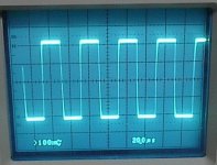
No Oscillation at all with any reasonable idle current now with latest changes. The ringing in the bottom half of the squarewave is most it does now, but like I demonstrated a few posts ago, only at normal idle current.
Of course, this ringing is the key to the oscillation that I experienced before. I need to eliminate the source of it.
Of course, this ringing is the key to the oscillation that I experienced before. I need to eliminate the source of it.
Hi,
About oscillation: what about changing C14's value - or completely remove it from circuit?
Your schematic shows R18 as 560r. I'd say that ~2mA (1.1V/560r) bias current for the drivers is too low. I'd rather try 50...200r as R18.
About oscillation: what about changing C14's value - or completely remove it from circuit?
Your schematic shows R18 as 560r. I'd say that ~2mA (1.1V/560r) bias current for the drivers is too low. I'd rather try 50...200r as R18.
salas said:In your schematic I would try C9=47uF, R10=4.7k trimmer pot, and R17+R24= single 2k7 resistor. And see if it cuts the bias effectively.
I will change C9 and see if this makes a difference. I realised too late that I should have configured the bias as you have detailed.
Oh well, there's always the new board revision. 🙂
John, I agree with DONK. Remove C14 from the circuit and see what happens. I assume that 560R for R18 is a typo, but this wouldn't cause it to ring I think.
Don S
Don S
The 47uF only substitution may work, if not, make a hardwired 'bug like' construction of the whole recommendation, just to test. Don't make any V2 board for such a small thing. I agree with the other guys to see about C14 too.
salas said:Bravo! THAT'S progress.
I'll say. All that messing around for one silly cap.
I have reduced R18 to down to 280 ohms (560R in parallel to the existing). No signs of instability. I will further reduce it to 220R a little later. I'm going to work on the resistor values for the Vbe also - Nico suggested that they may be too high.
Thanks for help, fellas.🙂
I'm very pleased with the results. It makes the time spent working on it worth it when it turns out well.
A little more tinkering and I'll post a revised schematic
MJL21193 said:
I'll say. All that messing around for one silly cap.
I have reduced R18 to down to 280 ohms (560R in parallel to the existing). No signs of instability. I will further reduce it to 220R a little later. I'm going to work on the resistor values for the Vbe also - Nico suggested that they may be too high.
Thanks for help, fellas.🙂
I'm very pleased with the results. It makes the time spent working on it worth it when it turns out well.
A little more tinkering and I'll post a revised schematic
ITS LIKE COOKING WITH GAS!!!!!
Its always a bit surprising from sim to bench. Typical stuff. I only patch the feedback after I see the finished real layout performance on the scope... I saw your thread only today. I see you use 30dB gain. What is the 8 Ohm power? How much is your feedback? Are you about to listen with those nicely curved 3ways with passive cross or you are building 6 channels to go straight to active?
- Status
- Not open for further replies.
- Home
- Amplifiers
- Solid State
- Help with this amp? A patchwork product of simulation