Nico Ras said:John you say the oscillation is only there when connecting the speaker, is the oscillation bigger on the input side of the 500 nH? Try using a 10 ohm resistor instead of the speaker, is the oscillation still there?
Hi Nico,
I have found the source of this oscillation: the 2 pole compensation. When I removed the second cap C4 (200pf) and R5 (10k, changed to 20K), the oscillation stopped.
Not sure why it works in the prototype and not here.
Further investigation is needed.
Nico Ras said:
There is one other area that I was never so sure of and that is the high pass T-section that you use in the top of the circuit.
Nico
HMMMM, something there caused 360 degree phase shift, I am not a pro-miller cap fan. You see all my designs use a very small miller cap if any.
Glad you found it, now throw it in the dustbin and update your circuit.
The T-filter I mean not your amp!

Kind regards
Nico
Nico Ras said:
HMMMM, something there caused 360 degree phase shift, I am not a pro-miller cap fan. You see all my designs use a very small miller cap if any.
Glad you found it, now throw it in the dustbin and update your circuit.
The T-filter I mean not your amp!
I can't blame the 2 pole compensation for this oscillation. Was maybe a coincidence that it stopped when I changed that.
I found that the oscillation came back when I tried to adjust idle current. There's a problem here, as I have the same symptoms on the prototype - as soon as I adjust the 1k pot on the Vbe to increase idle current, the amp starts to oscillate.
Changes to the schematic and board layout are coming. I have spent the evening working with the prototype and the simulator, and have made some improvements.
I have re-configured the Vbe multiplier, reduced current to the VAS, reduced current to the front end, eliminated the local feedback through the VAS and changed to single pole compensation.
I'll post the updated schematic soon.
Here is the new and improved schematic. Some further tweaking might be required, but I lack the precision equipment to make accurate measurements.
I'm working on putting a new sound card in my lab computer, as I (typically) burned out the old one. No big deal, just a cheap sound blaster. I will be able to do some measurements with RMAA.
The oscillation was a hard problem to fix. Working with the prototype and the simulator, I determined that I was running too much current through the VAS and the drivers. Every time I tried to increase idle current past 30mA, it would start to oscillate.
I looked at the current gain of the drivers - 40, and I looked at the gain of the outputs - 75!
Changes brought the VAS current down from 15.5mA to 6.8mA and the drivers current down from 14mA to 3.5mA at idle.
I completely eliminated the 2-pole compensation, as this was an additional cause of oscillation. For the LM394, I trimmed the input stage down from 3.3mA to 1.8mA, though 3.3mA would be good for the BC550 pair.
With these changes, simulated performance is actually better. Looking at the output with an oscilloscope (i khz squarewave)shows absolute stability.
Attachments
Hi John,
Well done! It is sometimes heartbreaking when you run into a snag like this. It is great that you could make all the changes without having to do a new PCB.
If you have a chance kindly run the simulation with and without U8 & 9 and compare the results. I am very interested to see if the two simulations differ considerably.
Nico
Nico Ras said:
If you have a chance kindly run the simulation with and without U8 & 9 and compare the results. I am very interested to see if the two simulations differ considerably.
Nico
Happy Christmas Nico,
I have sent you an email.
The cascode transistors are needed to use the LM394, as this is a 35V device. Also handy for the BC550, as this is a low voltage device too.
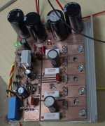
Here's a pic of the completed amp (actually in operation!).
Attachments
Congratulations John, very nice looking amp. I commend you on a job well done and hope that it compliments that beautiful pair of speakers.

Hi,
could someone explain why moving the bias currents down solves the problem? anything to do with the downward slope of the fT curves?
Now that we have stability, can we estimate the phase and gain margins?
What reactive loads should now be applied to simulate the speaker loads and cables?
I recall that the Symasym suffered similarly when the output devices were swapped. The solution was much different even though the symptoms (and reduced bias) were similar.
AndrewT said:Hi,
could someone explain why moving the bias currents down solves the problem? anything to do with the downward slope of the fT curves?
Now that we have stability, can we estimate the phase and gain margins?
What reactive loads should now be applied to simulate the speaker loads and cables?
I recall that the Symasym suffered similarly when the output devices were swapped. The solution was much different even though the symptoms (and reduced bias) were similar.
Andrew, I think so because the current bandwidth product increases with Ic. It also increases with temperature. The PNP is slightly worse than the NPN, so I guess a balance has to be struck. This may be the reason the smart guys are running several transistors in parallel to share current and temperature keeping everything stable at a relatively low Ic.
AndrewT said:Hi,
could someone explain why moving the bias currents down solves the problem? anything to do with the downward slope of the fT curves?
Now that we have stability, can we estimate the phase and gain margins?
What reactive loads should now be applied to simulate the speaker loads and cables?
I recall that the Symasym suffered similarly when the output devices were swapped. The solution was much different even though the symptoms (and reduced bias) were similar.
I can't claim it was an educated guess on my part, just it seemed the next logical thing to try.
Could it be entirely parasitic, due to the board layout, for example the proximity of the large output trace to the negative rail trace with the ground plane above?
To be honest, at maximum input level (therefore, maximum output current) there is still the "ghost" of the oscillation showing on the scope - very faint and non-latching.
As for loads I have been testing it with a 4 ohm (Re = 3.2 ohm) coaxial car speaker - a tough load. I can test it with a variety of cables and lengths.
While looking through simmed amps, trying to track down my oscillation problem, I looked at the symasym, and saw that at idle (idle current set to 83mA) the drivers are conducting ~33mA due to the 33R between them. It climbs to ~42mA at full output. Increasing this resistor to 200R reduced current and distortion.
Once again, I thought this was the simulator getting something wrong, but you mention the problem Andrew and it has me thinking. Looking at the Blameless, I see a 220R between the drivers.
With these high current gain outputs, how much bias is needed? My output devices conduct ~1A each at full output into an 8 ohm load. With gain of minimum 75, wouldn't 20mA from the drivers be enough? This give some headroom, about 1.5 times the minimum.
If this is the case, my 560R between the drivers is very close to the minimum, and this resistor should be reduced to ~220R (running at an idle current of ~93mA).
I will try this value and see if the oscillation returns.
MJL21193 said:
and this resistor should be reduced to ~220R (running at an idle current of ~93mA).
I will try this value and see if the oscillation returns.
Well, I tried it and the instability returned. I couldn't advance the idle current past 50mA when it would start to oscillate.
Installed the sound card in my lab computer and it's toast - distorting too high for RMAA to complete the sound card test. I got this from my brother (used) for free so no loss.
I figured out how to use my scope for square wave output without distorting: remove the attenuation pot I have (temporarily) at the input. It's impedance was screwing with the output from the calibrator. I know I should probably not use the calibrator as a function generator, but you've gotta do what you've gotta do. 🙂
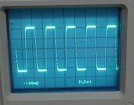
I have a couple of photos to share. The first is the output from the amp with a 20KHz squarewave, running with about 6mA idle current. Higher idle current was giving some ringing at the bottom half of the wave. I will get a shot of it running "normal" idle later, after it cools down a bit (gets REALLY hot amplifying this signal at full input, the reason I had to shut down).
Attachments
Hi John,
Do you have the last PCB design still intact?
If so, how does it perform compared to current PCB?
Still no snow where I live in Sweden 😡 😉
Edit: I would try to reroute the path to the VBE multiplier by using wires instead, just to see if it makes any difference.
Do you have the last PCB design still intact?
If so, how does it perform compared to current PCB?
Still no snow where I live in Sweden 😡 😉
Edit: I would try to reroute the path to the VBE multiplier by using wires instead, just to see if it makes any difference.
4fun said:Hi John,
Do you have the last PCB design still intact?
If so, how does it perform compared to current PCB?
Still no snow where I live in Sweden 😡 😉
Edit: I would try to reroute the path to the VBE multiplier by using wires instead, just to see if it makes any difference.
Hi 4fun,
Yes, I have the second prototype still, but it has MJL21193/94 for outputs. It is definitely more stable, but not completely.
Snow? I've had enough already. 🙂
Here's the amp running at about 60mA idle. Notice the ringing at the bottom. This is just waiting for the opportunity to break into full scale 1MHz oscilation...
Ideas?
Attachments
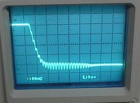
MJL21193 said:Last photo's a little blurry, nervous around some much raw power 😉 😉
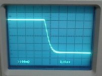
Here's the 10X magnifacation (sorry, meant 10X instead of 15X a couple post ago).
John, am I correct, that looks like about 1,6MHz is the scale 2.1uS/Div?
Try increasing the values of the emitter resistors to 0.47 Ohms or even 0.68 Ohms also move the zobel to after the inductor and check again for oscillation. Increasing the emitter resistor will provide a little more local feed-back. It will not change your output impedance by much.
I had the same problem when I started up my amp. Have you tried 100pF B to C on the VAS transistor?
Don S
Don S
Hi Nico,
The magnified scale is 2.1uS. When I say 1MHz, that's really a ballpark figure. I'd like to know if it's possible that this is the result of parasitic inductance/capacitance between the output trace and the negative rail.
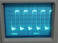
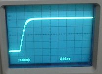
Here's a shot of the top half of the wave magnified 10X. No ringing.
The magnified scale is 2.1uS. When I say 1MHz, that's really a ballpark figure. I'd like to know if it's possible that this is the result of parasitic inductance/capacitance between the output trace and the negative rail.
Here's a shot of the top half of the wave magnified 10X. No ringing.
Attachments
Don S said:I had the same problem when I started up my amp. Have you tried 100pF B to C on the VAS transistor?
Don S
Hi Don,
Miller cap of 100pF is in place between the EF and the collector of the VAS.
- Status
- Not open for further replies.
- Home
- Amplifiers
- Solid State
- Help with this amp? A patchwork product of simulation