Donk said:Dear MJL21193,
Changing the Miller-cap to a two-pole compensation (see Slone) would decrease that 0.05%/20kHz THD to about 0.005%.
Worth to try.
Best regards,
Thanks Donk,
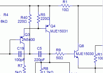
It reduced 20KHz distortion at 150 watts from .048 to .011 and at 4 watts from .017 to .001.
Do you have anymore good ideas? 🙂
I will implement this and post a full revised schematic shortly. In the meantime, here's how I did it:
Look at the values, especially R40. Is tis too low?
Attachments
PB2 said:
...and I've been meaning to mention that some claim that amps have large turn on thumps that do not use one on the diff pair, forgot to mention that earlier. The one on the VAS eliminates the large bootstrap cap. I perfer to eliminate electrolytic caps whenever possible.
If you're buying new outputs you might want to look into the thermal trak versions, which do provide diodes.
Hi Pete,
The turn on thump will not be an issue with this as I will use delayed relays on the outputs.
I really should use some of the devices I already have. On hand I have 4 pairs MJL4281A/4302A, 4 pairs MJL3281A/1302A, 6 pairs 2SC5200/2SA1943 and several MJL21193/94 plus many other (used) pairs from older amps.
AndrewT said:
no these drivers and most others have Cob~=30pF.
You should be looking at VAS and pre-drivers with Cob<=3pF.
One possibility?
2SA09140 - 150V, TO-126B, Cob = 5pF.
MJL21193 said:
You really need to consider the short circuit current again. I expect that this 50 mA device will not hold up. These are also better suited to designs with output stage triples where less current drive is required.
I think you mentioned that you don't expect to clip this amp, imagine a plug accidentally being pulled at the input or some other accident. You don't want it going up in smoke, obviously.
Pete B.
MJL21193 said:
Thanks Donk,
It reduced 20KHz distortion at 150 watts from .048 to .011 and at 4 watts from .017 to .001.
Do you have anymore good ideas? 🙂
I will implement this and post a full revised schematic shortly. In the meantime, here's how I did it:
Look at the values, especially R40. Is tis too low?
Move the right hand side of C5 to the output feedback point to include the output stage in the Miller loop. Stability analysis is now even more important.
Pete B.
Hi,
a 50mA device is adequate here if protection is properly implemented.
Assume 50mA through the VAS and gains of 100 @ the driver and 30 @ the output.
That equates to 150Apk of continuous short circuit current.
Most of these medium power devices will allow at least 100% of transient overcurrent while the fuses blow or electronic protection comes into action.
Normal output of 40Vpk into a 4ohm reactive load requires <=29Apk at the output. Assuming (slightly better gains to suit operating currents) of 35 and 150 at the output stages shows that VAS current should never exceed 5mApk (again a transient value).
PB2 said:
You really need to consider the short circuit current again. I expect that this 50 mA device will not hold up.
AndrewT said:Hi,
a 50mA device is adequate here if protection is properly implemented.
I'm at the mercy of what is available, gentlemen. If there are other, higher current choices, let me know. I have an order put together for Digikey that I can't put through, due to uncertainty about these devices.
Andrew, you mention protection. Is this fuses only, or do you mean a more active approach? I will have a sub-circuit board with the output relays and fuses.
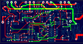
Here's a board layout. Power ground is not connected as this will be poured on the top layer (green).
Comments/opinions are welcome.
Attachments
IV protection on the output for short term transient, supply rail fuses for the medium term. You've already looked at that EF between LTP & VAS.MJL21193 said:
protection. Is this fuses only, or do you mean a more active approach? I will have a sub-circuit board with the output relays and fuses.
Only one left is VAS, but you're not happy with the distortion report.
AndrewT said:IV protection on the output for short term transient, supply rail fuses for the medium term. You've already looked at that EF between LTP & VAS.
Only one left is VAS, but you're not happy with the distortion report.
I'm exceedingly careful with my gear, so I don't see short circuit being something I need to guard against. If implementing effective protection off the main board is possible (fused output? possibly 5 amps), I'll do that.
With the relays, is it possible to switch them open when a higher than normal current draw takes place, or if the output is shorted at turn on? Would such a circuit react in time to be effective?
Hi John,
I've stated that I like fuses for simple home designs, however, I like them with a beefy output stage that can drive 2-1 ohms safely, then fusing for 2 or 3 ohms. Otherwise I believe that protection is needed. Calculate your fuses and resist the temptation to use larger ones.
Outputs, all of those are good, I'd probably go with the MJL3281A/1302A which seem to be the best fit and are available should you blow them out in this experimental design. I'd use MJE15035 for the VAS and yes the 15031 is probably fine for the driver, yet the 035 is better with its higher SOA and beta.
VAS: the very old traditional VAS for high power amps is the 2N3440/2N5416. These were high voltage 1A, 1-10W parts. I would not go lower than parts rated for 1.5A due to the short circuit considerations. What really matters is SOA, and I just look at how much current the part can handle at roughly the rail voltage, say 50V for purposes of comparision. You probably know that the right way to do this is to calculate exactly what you need to meet the electrical requirements, including fault conditions (at the highest operating temperature), with some margin. Typcial values are .1A - .3A. Many parts are tabulated here, and there are data sheets that you can take a look at:
http://www.ampslab.com/components_mediumpower.htm
Consider for TO-220, 2SA1011, 2SA1306, 2SA1930, and in a T0-126 the 2SB649A, but even these do not meet the worst case short circuit conditions without a protection transistor.
Pete B.
PB2 said:
Move the right hand side of C5 to the output feedback point to include the output stage in the Miller loop. Stability analysis is now even more important.
Pete B.
I only suggest this as an example for simulation, as it can be difficult to stabilize with load variations in real hardware.
PB2 said:I'd use MJE15035 for the VAS and yes the 15031 is probably fine for the driver, yet the 035 is better with its higher SOA and beta.
Hi Pete,
On the simulation, I only see Q4 (VAS) drawing 50mA at full power into a short circuit. I don't understand why this device has to have a high current rating. Something I'm not seeing?
BTW, It shows 3.5A through the drivers and 50A through each output.
Andrew says the VAS should have a low Cob, but doesn't my Q3 act as a buffer between the VAS and the LTP?
Thanks for the link, although I'd found it a couple years ago, added it to my favorites, then forgot it. I will order the 2SA1011/2SC2344 from there, as they seem reasonable for shipping ($5.00) and they use USPS as opposed to UPS (huge, unreasonable brokerage fee at the border with UPS).
This will leave me with 10 pairs of each for this and future projects.
For the outputs, I'll use the MJL3281A/1302A pairs.
Any thoughts or comments on my board layout? I have the differential inputs as separate Q's on the boards to provide more flexibility for device selection. I'm assuming that the LM394 has leads long enough to bend to match this pin-out.
PB2 said:
I only suggest this as an example for simulation, as it can be difficult to stabilize with load variations in real hardware.
I did this, but it made no difference with regards to distortion. This two pole compensation trick really pared down the HF distortion. While I made this change, I added an emitter resistor to Q4.
I believe we have this design well in hand now. Though I thought I would have started prototyping it on the weekend, I had to work on Saturday, ruining my fun.
At this point, I will wait for the new devices to arrive before I do anything.
MJL21193 said:
Hi Pete,
On the simulation, I only see Q4 (VAS) drawing 50mA at full power into a short circuit. I don't understand why this device has to have a high current rating. Something I'm not seeing?
BTW, It shows 3.5A through the drivers and 50A through each output.
Andrew says the VAS should have a low Cob, but doesn't my Q3 act as a buffer between the VAS and the LTP?
Thanks for the link, although I'd found it a couple years ago, added it to my favorites, then forgot it. I will order the 2SA1011/2SC2344 from there, as they seem reasonable for shipping ($5.00) and they use USPS as opposed to UPS (huge, unreasonable brokerage fee at the border with UPS).
This will leave me with 10 pairs of each for this and future projects.
For the outputs, I'll use the MJL3281A/1302A pairs.
Any thoughts or comments on my board layout? I have the differential inputs as separate Q's on the boards to provide more flexibility for device selection. I'm assuming that the LM394 has leads long enough to bend to match this pin-out.
Hi John,
Yes the very high simulated 50A current causes a large drop on the emitter resistor, but there will be beta droop and the current should not be that high. If everything goes fine and the fuses blow there should not be much of a problem. However you have to consider how long the fuse takes to blow and that the VAS and drivers have to survive this overload period. Fuses are slow, depending on percentage over the rating.
So, the at a glance, very much worst case, short circuit VAS current is, say the supply droops to 50 volts, the VAS saturates, and assume the low end of R9 is just 2 diode drops above ground, then the peak current is 50/R9 or 1A for 50 ohms, .5A for 100 ohms.
Refining this a bit, we could assume 20A in each output for an additional 5.4 volt drop on the emitter resistors, 1A in the drivers for 10V on the base stoppers, say 17V total including some for the BE diode drop, so peak R9 voltage becomes 33V, peak currents 33/R9, or 330 mA for 100 ohms, 660 mA for 50 ohms, not even half of our very worst case, still well over 100 mA. This is the peak during the time it takes to blow the fuse, obviously we don't want the transistor to blow before the fuse does. Remember that the SOA figures must be further derated for operating temperature.
Another case to consider is a shorted output, with an input signal that is the maximum before the fuse blows, say that causes an RMS current at the fuse rating, then look at the transistor voltage, current, and power in simulation.
Pete B.
MJL21193 said:
Andrew says the VAS should have a low Cob, but doesn't my Q3 act as a buffer between the VAS and the LTP?
Any thoughts or comments on my board layout? I have the differential inputs as separate Q's on the boards to provide more flexibility for device selection. I'm assuming that the LM394 has leads long enough to bend to match this pin-out.
Hi John,
Yes Q3 acts as a buffer.
The LM394s that I've used had about .5" leads, the pin out is in the data sheet of course. Two Q's back to back is fine, usually the flat sides would go face to face and you can put a tie wrap around them with a dab of thermal grease to keep them coupled. You may want to do some economy versions without the dual, this makes sense. I'm not sure if the LM394 will match up in any simple way if you do this, you could have two different positions and just populate whichever you use.
About your layout, have you read much about it?
Here are a few papers:
http://www.analog.com/library/analogdialogue/archives/39-09/layout.pdf
http://www.analog.com/UploadedFiles....aspx?url=http://www.analog.com/UploadedFiles
http://www.analog.com/UploadedFiles...g.com/UploadedFiles/Application_Notes/5008249
http://www.hottconsultants.com/pdf_files/june2001pcd_mixedsignal.pdf
Does this inspire you at all as far as neatness goes:
http://www.diyaudio.com/forums/attachment.php?s=&postid=614697&stamp=1112913063
I've not spent too long looking at your layout, I'd want a heat sink for the VAS and drivers, I think you said you had one, but just to be sure.
Careful how you pick off the feedback point, Self talks about this.
Many have commented, including Cherry, Self, and others, about how routing can impact distortion at these very low levels. Chassis grounding is very important, however you've got almost everything on the board which is good.
Keep high current traces away from low level traces, keep high current loops as short as possible.
It's good that you have the PSU caps and diodes on the board as it keeps the traces short. The junction of the PSU caps and the transformer center tap is the single point high current ground. Think of how the current flows in your design.
It would probably be helpful to have a few of the layout experts look over your next cut.
Pete B.
Hi Pete,
Thanks for the references, I need all the help I can get.
The pinout of the TO-5 LM394 is two TO-92's back to front, so that's how I have it on the board.
The board... I have been further refining it, moving components, trying to get as neat and simple as possible. But, as usual, I can't see everything. Help here from other, more experienced members, would be appreciated.
At one point I was tempted to scrap the whole layout, go back to the schematic and add 2 more pairs of output devices (as a higher output option - the sub amp looked at earlier). I may still do this, though it would increase the boards size quite a bit.
Otherwise, I've pretty much stalled, waiting for the parts to arrive. On a brighter note, I did make up a temporary power supply, using the transformer that will eventually power these amps.
Progress.🙂
The final schematic update? Maybe.
Not much in the way of changes - tidied up the two-pole compensation and swapped the VAS for the 2SA1011.
I still haven't started to prototype this design but have been steady working on a board layout. Maybe a bit of "putting the cart before the horse".
Not much in the way of changes - tidied up the two-pole compensation and swapped the VAS for the 2SA1011.
I still haven't started to prototype this design but have been steady working on a board layout. Maybe a bit of "putting the cart before the horse".
Attachments
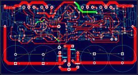
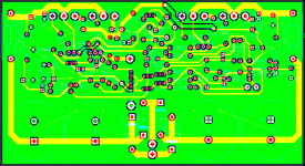
The latest board layout. Much improved over the previous efforts, with most of the routing on the bottom. The layout also follows the schematic, making for a more logical placement of components.
As recommended earlier, I've allowed space behind the output devices for routing of the power traces. I will attach these transistors to a thick copper heatspreader, which will be bolted to the heatsink.
As recommended earlier, I've allowed space behind the output devices for routing of the power traces. I will attach these transistors to a thick copper heatspreader, which will be bolted to the heatsink.
Attachments
- Status
- Not open for further replies.
- Home
- Amplifiers
- Solid State
- Help with this amp? A patchwork product of simulation


