You should start by drawing load line on the graph. Search for load lines, for the beginning. Here on forum you can find lots of wisdom.
That's what I did. I draw a line across 60mA and meet with 400v@ -70v point after I did the calculation for my output transformer. or did I do the wrong math.
Hey Globulator,
The Broskie idea is not the smartest even if wrapped in thousands of words and formulas. It is still far from good to drive a I/V stage with a triode-driver. A pentode/cascade/FET on the other hand is what can be looked upon as a current source and is what should be used here.
Remember you use a 4,7k series feedback element making things easier for the driver triode. So it might be looking into something like 7-10kohm. Although the one you use has a lousy low Ri CCS(made from a triode)on top. Didn´t it work to take the signal from the SRPP-output?
Yes obviously the interaction between the triode and the feedback is not such a good thing, but in principle I like the concept - a short, powerful DC coupled feedback making the output tube have low impedance. Like JB says - like a CF but without the costs.
My original SRPP in my diagram breaks with the partial feedback resistor because the DC connection means it's no longer an SRPP, and makes the top triode a bit useless - as you noted!
The initial idea was to control the driver's output impedance by using the SRPP as a low impedance voltage source and using a resistor (the 4.7k) to allow it to work with the feedback. (The take-off from the anode on the bottom triode or the cathode of the top triode didn't seem particularly audible when I tried it on my SE) - note I have not built this yes, still thoughts in progress.
Perhaps an ultralinear cascode driver may be the answer here, using the GU50 in easy to drive pentode mode.
I have about 500V for the GU50 but could raise that to 750V at a pinch as the supply in a voltage doubling arrangement already; so adding another pole is nothing - to jack it up by another 250V 😉. The supply would obviously become a bit wobblier then but that's not a problem here.
I'm stuck with an OPT that ran from 500V with a KT88 though, but instantaneous power would be impressive (depending upon iron), fine for music peaks. 😉
I'll have another go at rearranging stuff in the diagram and see what I get.
That's what I did. I draw a line across 60mA and meet with 400v@ -70v point after I did the calculation for my output transformer. or did I do the wrong math.
Why 60 mA and 400V?
Ok, let's you want to run it at 60 mA and 400V. Depending on load resistance the line will have different angles. Left limit is when it hits a graph for 0V on the first grid. Assuming symmetric drive you can find max negative swing, from the same point at 60 mA and 40V on anode, and to the right. You see now voltage and current swing on anode you get, and can estimate output power and percentage of distortions. Try different lines, for higher and lover load resistances. Which combination of output power/distortions do you like more?
Looking forward to see what you come up with in the next phase of your design.
Thanks RV!
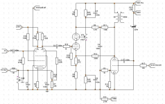
This is my latest doodle, as usual values are subject to experimentation, this is really a concept diagram:
It's a little simplified and has a cascode, not sure it all adds up yet but comments welcome. Input 6AR8, cascode tubes are 6n2p, OP = GU50
Attachments
and the first dot after R14
Oh yes - I must disconnect that or the idle will be a little high !!
Hi Wavebourn, the floating suppressor grid is an experimental mod I'm curious to hear after reading this: DECWARE - The Hazen Mod
it's an easy ground if it doesn't pan out..
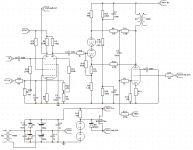
My simplification affectively puts the raw B+ over the rather PSRR prone cascode and then tries to null it out so I may go back to the original RC filter and an additional null for the B+, but it is simple so it's temping!
It effectively turns the amp into an audio modulated power supply over the driver/output tube stages, with the nested audio feedback via R11/R12 and the PSU feedback via C5/VR2.
I could probably delete R8 now too.
I'm a little concerned that overall system gain may be a little low now, I'm hoping the 6AR8 can give me some gain to cover that but I'm not sure, R9 is designed to allow the R12 feedback to be more effective but both actions reduce gain too.
Just thinking for a moment about power supply ripple rejection - PSRR I don't think I ever realised what subtle effect it has on the sound. Not the ripple, although that's important, but the hash that must be audible on even the best PSU rail.
For instance a normal common cathode amp has in general a 6dB PSRR, simply because it's a potential divider sitting in the middle.
But it isn't really is it? It's a variable potential divider that on the high (tube off) peaks has very very poor PSRR and on the low parts (tube full on) has much better PSSR, so the imprint of the PSU upon the musical trace varies dependant upon the level of the signal at the time. This also means that an SE amp is unbalanced for PSSR, but a PP amp will be worse at both +ve and -ve peaks, in a similar manner.
This fact makes it essential for best results to plan for and compensate for these effects - probably why the aikido works so well.
Has anyone else here considered the subtle tune that their power supply is playing as they listen to their amps? I know LC or RC circuits will always help, but then LF impedance suffers and the psu/hash waveform is still wrong, but just suppressed a little.
Why 60 mA and 400V?
Ok, let's you want to run it at 60 mA and 400V. Depending on load resistance the line will have different angles. Left limit is when it hits a graph for 0V on the first grid. Assuming symmetric drive you can find max negative swing, from the same point at 60 mA and 40V on anode, and to the right. You see now voltage and current swing on anode you get, and can estimate output power and percentage of distortions. Try different lines, for higher and lover load resistances. Which combination of output power/distortions do you like more?
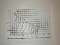
I re-do the chart again, aiming at -55v and have the following result. Please kindly check.
-(650-400).1000/(40-110) = -250,000/-70 = 3,571
Attachments
Looks better when hotter, but I personally would prefer load about 4K
Also, I am not afraid of negative feedback and A2 drive. 🙂
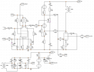
Here is interesting schematic, though in right-handed mode:
http://wavebourn.com/forum/viewtopic.php?p=25154
Also, I am not afraid of negative feedback and A2 drive. 🙂
Here is interesting schematic, though in right-handed mode:
http://wavebourn.com/forum/viewtopic.php?p=25154
Last edited:
Looks better when hotter, but I personally would prefer load about 4K
I only have 3.5K on hand
Also, I am not afraid of negative feedback and A2 drive. 🙂
Here is interesting schematic, though in right-handed mode:
www.wavebourn.com • View topic - GU-50 Single Ended Amplifier Design
I read the thread but there are lots of schematics along the way. Please specify. Thanks
I read the thread but there are lots of schematics along the way. Please specify. Thanks
The whole thread is useful.
If you have only 3.5K, use it. Try, listen, then you will decide where to go next.
I re-do the chart again, aiming at -55v and have the following result. Please kindly check.
-(650-400).1000/(40-110) = -250,000/-70 = 3,571
This isn´t impressing and GU50 isn´t well suited for triodestrapping. On one side you swing from 400-150=250V on the other 575-400=175V. This means in the ballpark of 9% 2nd order distortion at clipping just over 6W.
Bad effiency and bad result.
Find another tube if you want to make use of your 3,5k tranny. The Chinese version of EL156 comes to mind. With GU-50 go Right-Handed Triode or Schade.
Hello Albert,
It is very obvious to see the kind of distortion looks like after the load line is plotted on the plate characteristic graph. In the grid voltage approaches to ZERO, the gap of the curves are wider and it become narrow when it approaches the more negative side.
Therefore, it is a game of compromise - higher the output impedance, lower the distortion, but lower the output power and higher the damping factor. Then, lower the output impedance, higher the distortion, but higher the output power and lower the damping factor.
Anyway, I believe you have better understanding how the power amplifier works now.
By the way, try to plot the load line of 3.5K output transformer for the 2A3 and 300B tubes and see how the distortion looks like. Also, shift the bias point to see what difference it makes.
Johnny
On one side you swing from 400-150=250V on the other 575-400=175V. This means in the ballpark of 9% 2nd order distortion at clipping just over 6W.
Thanks and would you tell me more why 575-400/ not 650-400 ?? There should be something I miss and I should learn.
Find another tube if you want to make use of your 3,5k tranny. The Chinese version of EL156 comes to mind. With GU-50 go Right-Handed Triode or Schade.
I don't have EL156 but I have some 6P45C.
Hello Albert,
It is very obvious to see the kind of distortion looks like after the load line is plotted on the plate characteristic graph. In the grid voltage approaches to ZERO, the gap of the curves are wider and it become narrow when it approaches the more negative side.
Therefore, it is a game of compromise - higher the output impedance, lower the distortion, but lower the output power and higher the damping factor. Then, lower the output impedance, higher the distortion, but higher the output power and lower the damping factor.
Anyway, I believe you have better understanding how the power amplifier works now.
By the way, try to plot the load line of 3.5K output transformer for the 2A3 and 300B tubes and see how the distortion looks like. Also, shift the bias point to see what difference it makes.
Johnny
Thanks buddy.
Thanks and would you tell me more why 575-400/ not 650-400 ?? There should be something I miss and I should learn.
[/B]
I believe you need to watch out the same swing for the positive and negative is the same and not exceeding 0V to avoid driving it to A2 region.
Johnny
The whole thread is useful.
If you have only 3.5K, use it. Try, listen, then you will decide where to go next.
Try the right-handed mode with the 3.5k ???
- Status
- Not open for further replies.
- Home
- Amplifiers
- Tubes / Valves
- Help with these Russian GU50 tube amplifier