I will check the protection circuit as you have instructed . One thing I want share with you is the the VFET out the pre-amp the power amp works very well the relay engages as it should the sound is awesome through headphones , when you turn off the power while monitoring the relay contacts you can see them move back to off position as soon as the power is turned off but the strange you notice is that about 10 sec the relay coil again get energize a few seconds and then permanents disengage is this normal ? I am worried that when the VFET are in place if this same thing happen it might damage the VFETs
Some typos in your #41:
A situation happens where the prot circuit is at ease, while it does not sense something else. But what?
I prepared some drawings about the prot circuit today but left them on my work. I'll post them tomorrow.
It is important that the prot circuit behaves as expected, so have that one well tested as by #40.
I've also engaged into a solution during the testing phase without the V-fets but with imposters instead: using small signal J-fets along with Sziklai current boosters. Some calculations needed, resistor networks to have things behave as if and more protection parts are in my head, but not on paper yet. And Lo & Behold, that won't act as V-fets but as a measurement substitute only. Cheap parts like the 2N5458/2N5461 and complementairy Darlingtons (suggestions are welcome) for the current demand. Sort of Hiraga output. (I really don't like the idea to use mos things...)
Ehmm...?is the the VFET out the pre-amp the power amp works very well
That's what should happen.when you turn off the power while monitoring the relay contacts you can see them move back to off position as soon as the power is turned off
That's odd indeed - should not happen.the strange you notice is that about 10 sec the relay coil again get energize a few seconds and then permanents disengage
A situation happens where the prot circuit is at ease, while it does not sense something else. But what?
I prepared some drawings about the prot circuit today but left them on my work. I'll post them tomorrow.
It is important that the prot circuit behaves as expected, so have that one well tested as by #40.
I've also engaged into a solution during the testing phase without the V-fets but with imposters instead: using small signal J-fets along with Sziklai current boosters. Some calculations needed, resistor networks to have things behave as if and more protection parts are in my head, but not on paper yet. And Lo & Behold, that won't act as V-fets but as a measurement substitute only. Cheap parts like the 2N5458/2N5461 and complementairy Darlingtons (suggestions are welcome) for the current demand. Sort of Hiraga output. (I really don't like the idea to use mos things...)
The C417/R421 combo should prevent this. C417 is 'large' (10μF) to span this time. With a 50V spec, this can become a suspect after some time. Better repalace with 10μF/100V tropic (105°C) grade.the relay coil again get energize a few seconds

I think I have a later production SONY TA 5650 On the power supply board there is an additional JFET transistor marked Q 409 2SK23A what is the purpose of this JFET? The service manual I have does not show this transistor on the power supply board . When I was rebuilding my TA 5650 Power supply board I replaced all the electrolytic caps and transistors on it . The transistors I replaced: The 2sk23a JFET I replaced with NTE 312, the 2x C1124 with BD 139G , 2x C1364 with 2x NTE 293 .
You advised to replace the C 501 on the power amp driver board to a non polar 470 uf , the present one in there is a 470uf/25v polar . I don’t have any 470uf non polar cap but have 220uf/25v non polar caps can I use 2x220uf non polar caps in parallel to build up uf to 440uf which is near 470uf ?
I really applaud you for the great very easy to follow diagram much easier to understand than the service manual and your great explanation how the protection circuit works in this amp !🙏👍😊
Huh???there is an additional JFET transistor marked Q 409 2SK23A
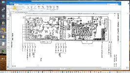
I have several service manuals, drawings and pictures collected but none have a Q409 2SK23A Jfet in the power supply.
Sony did use these as a current source in several designs. But there is no good reason for a CS in the 4650/5650 power supply.
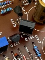
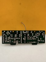
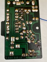
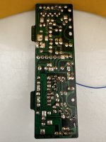
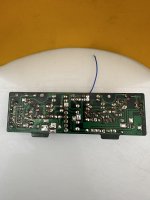
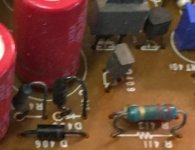
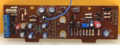
Being very curious, can you post a picture of it (both top & btm sides)?
In the first production, a 220μF/6.3 was used, and is suitable too. So only one 220μF/25 is sufficient. τ with 10k//10k*220μ=1sec, 470μ is 2sec, hardly any difference. The value is not that important, the nonpol quality is!I don’t have any 470uf non polar cap but have 220uf/25v non polar caps can I use 2x220uf non polar caps in parallel to build up uf to 440uf which is near 470uf ?
I'll pm you some other readings.
Cheerio!
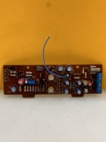
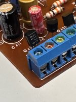
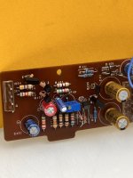
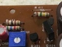
Hi citizen , here are the pics of the power supply board I replaced some the the transistors recently with better ones! All are new except the A735 do you know a sub for this one ? The Q 409 was a heft 2sk42 not 2sk23a looking from front of this transistor the pins allocation were GSD GATE , SUPPLY, DRAIN I replaced it with J113 jfet with pinout DSG you can see it in the pics . With new close orig specs transistors the relays no longer engage for few secs after pwr to the amp is shut off . Now what happens is that after the first time you install one channel FETs the relay engages but when you turn up volume it disengages if you lower the volume very low like at 7 -8 clock position the relay again engages but again disengages of volume is increased and after that it stay disengaged unless you remove the FETs without FETs everything seem perfect gate ,source voltages at VFET sockets are all correct ! I am thinking removing the 68 ohms/5w protection resistors one each in series in the +- 44dc power supply line to the power board to protect the VFETs from drawing excess current in case there is problem with the repair and hence saving them from destruction! I am thinking the resistors are limiting the current to VFETs hence the relay disengages when volume is increased . With the new better specs transistors in power supply board these protection resistor no longer get hot . What is your expert advice as to what might be happening when VFETs are installed for the relay to disengage ?
Attachments
Alas... I knew these things in the 80's and 90's, but my knowledge is outdated. Other members here maybe?A735 do you know a sub for this one ?
Ah, that's curious! The 2SK42 is a very low Vds type (10V!, Sony breed)), so odd to find it in the supply.Q 409 was a heft 2sk42 not 2sk23a
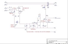
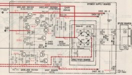
And on this supply, there's also this Q409.
But I have not found a circuit drawing or service manual where this J-fet appears.
Anyone out there???
I'll try to reverse engineer that circuit diagram this week. Some manipulations with the pictures provided.
I guess it's used as a current source.
when you turn up volume it disengages if you lower the volume very low like at 7 -8 clock position the relay again engages but again disengages of volume is increased
Pretty much sure these protection resistors also prevent the outputs landing on the nominal low offset (<< 1Vdc).removing the 68 ohms/5w protection resistors one each in series in the +- 44dc power supply line to the power board to protect the VFETs
Did they got hot? Hmm...With the new better specs transistors in power supply board these protection resistor no longer get hot .
Have these threads as guides:
Andrew 1
Andrew 2
Knowledge is standing on the shoulders of other giants for a panoramic view. Andrew prooved this being one for me.What is your expert advice as to what might be happening when VFETs are installed for the relay to disengage ?
Your question is a bit confusing: do you mean what is happening with the V-fets if the relay disengages for an unknown reason, or what happens during the startup/shutdown sequence when the relay is disengaged?
For whatever any reason or Saturn V rocket to be projected to the moon or any other twist of mind and universe, the gate supplies MUST be at par within a single wave of the ac output of the transformer.
Last edited:
Yes, a current source.
Some additional files.
Some additional files.
Attachments
-
 5650_PScir.jpg103.8 KB · Views: 65
 -
 5650_PS.jpg90.1 KB · Views: 65
 -
 5650_PSpcb.jpg473 KB · Views: 56
 -
 5650_PScomp1.jpg32.1 KB · Views: 56
 -
 5650_PScomp2.jpg12.2 KB · Views: 58
 -
 3336.jpg237 KB · Views: 57
 -
 3340.jpg203.4 KB · Views: 62
 -
 33.jpg205.9 KB · Views: 60
 -
 5650_PScircuit_Q409_2SK42.jpg105.2 KB · Views: 66
 -
2SK42_Book1999.pdf99.9 KB · Views: 209
- Home
- Amplifiers
- Solid State
- Help with Sony TA4650 VFET amp high power supply voltage