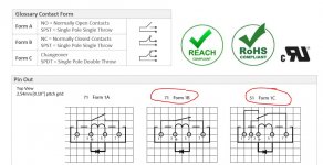
Muting always involves either shorting the signal (preferred option) or having a series switch of some kind. Relays are the simplest solution.
What about single in-line (SIL) relays. They look like SIL IC's and are very thin. You would need four for four feeds as they are normally single pole. Very slim though.
What about single in-line (SIL) relays. They look like SIL IC's and are very thin. You would need four for four feeds as they are normally single pole. Very slim though.
Attachments

Looks like an ideal solution but I'm going to live with it and see if it bothers me.
Thanks for all the help guys! I'll post a picture or two if I remember to do it.
Thanks for all the help guys! I'll post a picture or two if I remember to do it.
I'm going to try your SIL relays Mooly. I already forgot to turn off the low frequency amp first once and got some scary cone movement on my big speakers
Is there anything special that I need to know to use them? Do they come in 24v? Or 12v, either would work.
I can use a the builtin delay circuit to keep the output shorted at turn on, but how do I delay the turn off until they are shorted?
Also, the preamp is overall pretty darn quiet, as quiet as I had really hoped for since I'm using a regulated wall wart type supply. There is a light amount of white noise barely audible right at the tweeter, but I'm getting a slightly louder bit of hum that sounds like 60Hz. It's just barely audible at the listening position with no music playing. Any recommendation to reduce this as much as possible?
This is the supply I'm using GST60A24-P1J: MEAN WELL : 24 Volt 2.5 Amp 60 Watt Regulated Switching Table Top Power Supply : Power Supplies & Wall Adapters
I used a single star ground for all ground connections, audio and power
I have placed a 100uf electrolic and a .1uf mylar (I didn't have any ceramic) across the output of the supply. And 47uf across the input and output to ground of the regulator for the 12v feed.
Any suggestions? And again, thanks for all your help.
The SIL relays come in many different types so its a case of choosing a suitable coil voltage and preferably also a high coil resistance (if there is a choice) to minimise current draw.
A good turn on delay circuit would also normally have a virtually instant 'off' so that it drops the relay within a few milliseconds of mains power being removed. You can come close to that by feeding the relays from a power supply with a small reservoir cap.
That could be more difficult to arrange if the SMPS is the only supply because the output voltage will probably collapse fairly suddenly. Its going to be trial and error and seeing what works. You could perhaps feed the preamp from a series resistor/diode and cap feed to maintain its power for a few seconds and feed the delay circuit direct from the SMPS.
60Hz hum (pure and deep, not a buzz) suggests a true ground loop somewhere or even stray radiated pickup. The SMPS will be generating much higher frequency noise so that wouldn't be a suspect as such. Look at any mains grounds and whether any loops exist.
Ok, my response got deleted and I'm typing on a phone so I'll make this short😡
I'll try trial and error when I get the relays. Do I connect signal to common or is there a way to keep the signal out of the relays?
It definitely sounds like hum not buzz. It pretty low level but is present in both the woofer and mid of my three ways. two separate amps power the speakers. One for woofer and one for m/t section. Sources run through a mini dsp 2x4hd then into the pre. Source is a Mac mini and marantz receiver for tv. Everything is plugged into a power conditioner including the cable box. Any ideas?
The relay needs to have the contacts as normally closed so that it shunts the signal to ground (make sure the preamp is suitable for this method).
When the delay time is up the contacts open and remove the short. These two types are typical arrangements.
Standexelectronics PDF
The hum is near impossible to diagnose at a distance. Amplifiers and preamps don't themselves hum... it is getting into the audio path either via an input or via the leads themselves.
This covers many causes:
Attachments
Thanks. So there is nothing connected to the normally open right?
Interestingly I turning my stereo on today and there is basically no hum. There was when I first inserted the pre. It was low level but there. The only thing I did differently was flip on an amp that I haven't used in a while to see if it was plugged in, then turned it off.
Now, I can hear a light hiss that was more masked before. It is from all three drivers. Is there any way to help reduce this beyond what I've already done? I've seen people insert a series resister into the filter at the PS output? Larger caps? Replace the small Mylar with ceramic?
I'll probably build a linear supply eventually but I'd like to get this as good as possible for now. Thanks
Leave the normally open pin floating.
I would doubt the hiss is power supply related tbh. It would have to be a really noisy rail to do that. You could try a resistor/cap combination I suppose, at least it would give a clue.
The trouble with SMPS is that the noise is very hard to attenuate because of its fast rise times. Slapping more capacitance on the rail may not achieve much. The resistor adds a bit of impedance and does allow the cap to work much better. You can even cascade stages, so R/C and R/C and so on, each one giving a cleaner supply. A small electrolytic of around 47 or 100uF in parallel with a series 0.1uF and 1ohm would probably work well. The 1 ohm adds enough impedance to stop any ringing that a small cap on its own might cause.
Thanks mooly. So the .1uf should be in series instead of in parallel with the larger cap? And the series resistor is placed before the 47-100uf Creating a low pass correct?
It's not too bad at all and not audible unless I put my ear close to the drivers. Considering I don't know what I'm doing I'm pretty happy😉
It's not too bad at all and not audible unless I put my ear close to the drivers. Considering I don't know what I'm doing I'm pretty happy😉
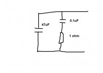
Yes 🙂 you also have your series resistors in the supply. The above was just referring to each decoupling cap combination.
1 ohm is as good as anything for starters. If it drops little voltage then you could try a little larger value, say 2.2 or 3.3 ohm.
I'm having trouble determining the required wattage for the resistors. Based on my power supply 24v @ 2.5a I would need a 2.5 watt resistor to handle the full current capability of the supply. So 3 or 5 watt right? But then what about the parallel resistor?
A 5 watt sounds big to me. Do I instead need to determine the actual current draw of the circuit?
A 5 watt sounds big to me. Do I instead need to determine the actual current draw of the circuit?
Yes, you need to measure the current draw. Given that this is low level small signal stuff the current draw should be low. If it draws quarter of an amp then that would be under a tenth of a watt for a 1 ohm resistor.
Will do. The spec sheet for the tube says that the heaters draw .3 amps at 12.6v. There are four tubes. So I thought it would at least draw 1.2. But I will measure it when I open it up again
I didn't realise the preamp was valve based tbh.
That changes things a little because you must ensure the heaters stay with the correct operating voltage, and that of course puts limits on how high a resistance you can use.
That changes things a little because you must ensure the heaters stay with the correct operating voltage, and that of course puts limits on how high a resistance you can use.
Yes. And the plates cant go any lower really. A CSS plate load keeps it around 20v and I'd assume that's the minimum. (I scaled a circuit from park audio preamp).
I could conceivably adjust the 12v regulator circuit so it drops less voltage but I don't want to starve the plates any more.
How much will the 1 ohm drop? 2.5v if it's drawing 2.5 amps correct?
I could conceivably adjust the 12v regulator circuit so it drops less voltage but I don't want to starve the plates any more.
How much will the 1 ohm drop? 2.5v if it's drawing 2.5 amps correct?
- Status
- Not open for further replies.
- Home
- Source & Line
- Analog Line Level
- Help with one button relay input switching