So I have increaced my class AB amp biasing, Much more current and is idleing at 10watts.
However, NPN and pnp are not ballanced. One side drwas more current which is pnp and draws about 20-40ma more
My biasing setting is pretty much same as the honey badgers adjustible vr at
Q13.
http://www.diyaudio.com/forums/solid-state/211905-diyab-amp-honey-badger-build-thread.htm
I wounder how I can solve this and make both sides use same current. Or are there alternative ways I can biasing this into near class a biasing?
I have tired to use base bias to bias the transitors, with a 56K to bias my npn decive and zero resitor for pnp device the amp is still drawing more current on pnp side. I tried removing bias transitor for two diodes instead and use the good old base bias again, still same results pnp draws more current. Not only my amp meter shows up as more, but my temp meter shows that pnp is also 3-4c hotter
Last edited by a moderator:
Hi,
With no load its impossible to have different bias currents.
With a load it is, implying a static DC offset voltage, fix that.
rgds, sreten.
With no load its impossible to have different bias currents.
With a load it is, implying a static DC offset voltage, fix that.
rgds, sreten.
No load?
I have a 8ohms speaker running, and the machine seems to be working fine with extra 20ma on one side (1watts approximate duall 50volts)
So if it runs fine and I get no blow ups with increaced bias then I wouldn't bother fixing the idle current
I didn't get a subscription sent to my mail, so I couldn't reply earlier
Static dc voltage offset, right, So I tune my dc voltage untill idle current is same on both sides, but whats the side effects of this? How does it weigh out? Same idle current is more improtant or DC offset voltage
I wanted a solution that keeps my dc offset at zero
Last edited:
No, you set the DC offset at the speaker terminal output to be zero volts. The current between each half should be pretty much equal under those conditions. If its not then we need to see the circuit of the amp to see if anything could be causing the imbalance.
I can think of side effects, from offset voltage, since the voltage slightly pulls the speaker up or down, it causes tension in the cone, thus the cone will move foward or backwoards faster than normall, causing distriotion.
I think I have tried everything I can, So I think its normall I tried changing resitors and bascically did all I can on trying to balance out the current. I think its normall for 1w extra on one side
I think I have tried everything I can, So I think its normall I tried changing resitors and bascically did all I can on trying to balance out the current. I think its normall for 1w extra on one side
With NO load what is the DC offset at the speaker terminals? If the DC offset is OK then the current from the -rail to the +rail has to be the same in the PNP and the NPN output transistors.
Some AB amplifiers don't like to be biased hotter than what they're designed for. Put the idle current back to the stock setting and see if your problem disappears. I've seen many amps on the bench where the distortion goes up if the idle current is increased much past the factory setting.
Craig
Some AB amplifiers don't like to be biased hotter than what they're designed for. Put the idle current back to the stock setting and see if your problem disappears. I've seen many amps on the bench where the distortion goes up if the idle current is increased much past the factory setting.
Craig
So at stock settings class ab biasing 20ma both sides, no current plorbem.
Without input but with a 6ohm speaker its zero volts, or are you asking me a voltage reading without any speakers attacthed? Thats seems a bit dangerous so I'll plorbally not try that.
I'm currently running 11-12watts ilde and heat sink goes to 36C while room temp is at 20C. No plorbem and the amp sounds better, so I'll probally leave it here or even go a bit further with biasing. Its already running for more than 1and a half hour so no doubt this is running fine 😀
Setting the DC offset without a load is the normal way to do solid state amplifiers, tube amps need the load. The load may obscure a problem as it may be loading down the offset voltage.
Check out the subject of "Gm doubling" and maybe you'll recognize the problem you are having with increased idle current.
Craig
Check out the subject of "Gm doubling" and maybe you'll recognize the problem you are having with increased idle current.
Craig
ok thanks for the info
" The problem of gm doubling lies in the discontinuity in transconductance and in output impedance in a class-AB power amplifier's output waveform, as the amplifier shifts from class-A to class-B. At idle and up until the output stage departs from class-A operation and enters class-B mode, the two active output devices combine their transconductance, hence the term, “gm doubling.” With only one output device active, the gm halves and output impedance doubles, and the eternal load effectively appears to halve in resistance. Since both output devices enter and exit class-A, two discontinuities result near the transitions from positive to negative output voltage swings. The ear hears these sonic speed bumps and complains, much like your hand encountering cracks in an otherwise smooth surface."
http://www.tubecad.com/2015/10/blog0331.htm
From my understanding this only happens to class ab amps, class a amps are biased high and it takes a lot of volume to make it turn into ab amplification. Furthermore, I do not think my plorbem is related to gm doubbling, it is related to the circuit it self, where the temp control amplifier diode setup is the troubble, as the diode in Collector and emitter are diffrent, it will cause npn and pnp have diffrent idle current
Last edited:
I can think of side effects, from offset voltage, since the voltage slightly pulls the speaker up or down, it causes tension in the cone, thus the cone will move foward or backwoards faster than normall, causing distriotion.
http://www.diyaudio.com/forums/solid-state/116731-can-d-c-offset-cause-non-linear-distortion.html
I think I have tried everything I can, So I think its normall I tried changing resitors and bascically did all I can on trying to balance out the current. I think its normall for 1w extra on one side
Is there a circuit diagram of the amplifier in question available so that we can see if there is any obvious reason for the imbalance ?
(And obscure reasons on a diy amp could be something like parasitic oscillation caused by connecting the meter leads to different points of the circuit)
So I have increaced my class AB amp biasing, Much more current and is idleing at 10watts.
However, NPN and pnp are not ballanced. One side drwas more current which is pnp and draws about 20-40ma more
My biasing setting is pretty much same as the honey badgers adjustible vr at
Q13.
http://www.diyaudio.com/forums/solid-state/211905-diyab-amp-honey-badger-build-thread.htm
I wounder how I can solve this and make both sides use same current. Or are there alternative ways I can biasing this into near class a biasing?
I have tired to use base bias to bias the transitors, with a 56K to bias my npn decive and zero resitor for pnp device the amp is still drawing more current on pnp side. I tried removing bias transitor for two diodes instead and use the good old base bias again, still same results pnp draws more current. Not only my amp meter shows up as more, but my temp meter shows that pnp is also 3-4c hotter
The link does not work so it is not clear what your circuit looks like.
The symptoms you have described look consistent with running a single pair of output devices at 300 m.a.
The output current of a transistor versus base voltage graph has a curved shape in the turn on area and a steep slope beyond that. Trouble arises if the crossover point is pushed to a region where the slope is steep.
With 0R22 emitter resistors 100 m.a. of standing current is about optimum for a single output pair and like the Honey Badger three pairs would be needed for an output standing current of 300 m.a.
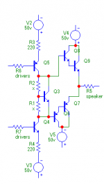
Heres my circuit Q3 is acting like as transitor diode. I reckon this circuit is quite simular to the Honey Badger ab amp, at the biasing control q3 and q13 for honey badger
http://www.diyaudio.com/forums/solid-state/211905-diyab-amp-honey-badger-build-thread.html
Thanks for the help guys
300ma? I only got mine biased to 110ma, at 50volts which is about 11 wats
http://www.diyaudio.com/forums/solid-state/211905-diyab-amp-honey-badger-build-thread.html
Thanks for the help guys
300ma? I only got mine biased to 110ma, at 50volts which is about 11 wats
Attachments
Q3 acts like a voltage regulator, actually a shunt regulator.
It tries to maintain the same voltage across it's C to E terminals.
The voltage required is referred to as bias voltage.
That bias voltage needs to match the two voltage drops across the output darlingtons.
Your Darlingtons do not have any output resistors (emitter resistors). This can make the output current unstable, so much so that the output Darlingtons could blow up !
I am not using darlingtons, Its a tip41c connected to a tip3055. So if I use some emitter resistors you reckon I could balance out the voltage? Any other ways? I don't really like putting my emitter resitors in there
That's a pretty standard Vbe multiplier... though it's hard to tell why your bias tops out at 110 mA (measured how?) when you're leaving out the important details like R1/R2 and Q6-9 emitter resistors.
Anyway, as stated before bias in the upper and lower half can only ever be inequal if output DC offset is nonzero. In this case, current imbalance is going to be ΔI = Voffset / Rload,dc. So a 20 mA offset with a nominal 8 ohm, 6.3 ohm Rdc speaker would have to be caused by a ~126 mV offset. There are some input / feedback configurations which may exhibit offsets that high when not adjusted properly, but you'd normally be using one that drops DC gain to unity (i.e. output offset = input offset), in which case I would suspect either a DC-coupled input left open (always short for adjustment) or an oscillation issue. Hard to tell without a schematic at hand.
EDIT: You really don't have any Q6-9 emitter resistors?! How are you even measuring bias level then? (Don't say with a multimeter in current mode. Then the current shunt is your emitter resistor.) Plus, isn't bias terribly unstable like that?
Not having any emitter resistor between Q6/8 is a pretty big no-no. They won't be able to suck out base charge fast enough like that, which will give bad high-frequency shoot-through. IOW, 20 kHz at higher power will tend to make your output stage run hot and go bang.
Suggested values: 0.22R for each of the outputs, plus 100-220 ohms in between the drivers. More towards the lower end. TIP41Cs seem a bit oversized (read slow) as drivers, at least use something in the 4A class like TIP31C if you don't have newfangled parts like MJE243/253 or MJE15034/35.
Last edited:
So my current dosen't tops out at 110ma, I can go higher if I want, the drivers get hot about 36-40C at a 20c room temp and the hottest resitor is 45C which is a half or quarter watt one.
I am running fine with a slight 20ma diffrence in npn and pnp, its working fine so I'd probally not bother about this plorbem.
The way I measured is connect two amp meters, in series with the postive voltage and negative voltage feed into the amp
R1/R2 is pretty much 2-2.3Times more with the R2 resitor compared to R1
R2 bigger than r1 (This is where the biasing happens, if I go out of range it drives into saturation or it goes back to class ab)
Meausring the BC voltage and CE voltage of output stage pnp transitors they are less voltage than npns, probally due to more idle current more load?
Last edited:
Heres my circuit Q3 is acting like as transitor diode. I reckon this circuit is quite simular to the Honey Badger ab amp, at the biasing control q3 and q13 for honey badger
http://www.diyaudio.com/forums/solid-state/211905-diyab-amp-honey-badger-build-thread.html
Thanks for the help guys
300ma? I only got mine biased to 110ma, at 50volts which is about 11 wats
There are no emitter resistors to provide local feedback - this is a thermal consideration.
The voltage drop across emitter resistors should be 26 m.v. which is to match the thermal voltage of a transistor emitter diode at room temperature.
The nearest standard value you need for the current you are using is 0R22.
Could we please agree to give each other some time to get the editing sorted out?
Differing Vbc suggests DC offset or supply voltage asymmetry WRT ground.
How exactly does that look? It may or may not be low inductance. (You know, commercial amp makers actually go to the trouble of twisting supply leads.) Less critical if the amp has on-board buffer capacitance. Otherwise excessive supply inductance is not exactly going to help stability.The way I measured is connect two amp meters, in series with the postive voltage and negative voltage feed into the amp
With no emitter resistors, you are at the mercy of transistor beta (squared for a Darlington), which does tend to be higher in pnps for complementary parts. You don't generally want to be depending on a rather variable parameter like that, hence some Re is generally applied. I don't think you can generally get away w/o them, except with very tight thermal coupling (e.g. all on one die in an IC).Meausring the BC voltage and CE voltage of output stage pnp transitors they are less voltage than npns, probally due to more idle current more load?
Differing Vbc suggests DC offset or supply voltage asymmetry WRT ground.
Yeah, why even bother the others with your "non-plorbem".I am running fine with a slight 20ma diffrence in npn and pnp, its working fine so I'd probally not bother about this plorbem.
Ok so those emiter resitors for tip41c are 68ohms originally and I took them out cause it sounded better afterwords.......
Yes of course
Could we please agree to give each other some time to get the editing sorted out?
Yes of course
- Status
- Not open for further replies.
- Home
- Amplifiers
- Solid State
- Help With My Class AB Biasing, Unbalanced npn, pnp current