..............The voltage required is referred to as bias voltage.
That bias voltage needs to match the two voltage drops across the output darlingtons.
Your Darlingtons do not have any output resistors (emitter resistors). This can make the output current unstable, so much so that the output Darlingtons could blow up !
you have drawn Darlingtons.I am not using darlingtons, Its a tip41c connected to a tip3055. So if I use some emitter resistors you reckon I could balance out the voltage? Any other ways? I don't really like putting my emitter resitors in there
draw a proper driver + output pair for your output stage.
And put in emitter resistors before you blow up your amplifier.
Listen and implement.EDIT: You really don't have any Q6-9 emitter resistors?! How are you even measuring bias level then? (Don't say with a multimeter in current mode. Then the current shunt is your emitter resistor.) Plus, isn't bias terribly unstable like that?
Not having any emitter resistor between Q6/8 is a pretty big no-no.
Yeah, why even bother the others with your "non-plorbem".
Because I spent allot of time tyring to get this happen and I thought others might have an idea on this. And I found out at the end that it works fine with extra current
It works fine wihout emitter resitor for tip41c and had ran for 2 years no plorbem, class ab mode, and juiced for 11watts idle still allright, So I'll look to see if the plorbem disaperas once I add the emitter resitor back in
Also my bias is stable, it dosen't go up when temp goes up
Q5 and Q4 are buffers passing constant current of a considerable amount. What I see happening is Q8 and Q6 being turned hard on and getting hot as the result.
Seemingly Q6 is drawing so much current as to starve the emitter of Q3 which has compromised its' operation. The energy source in a transistor is the emitter.
There may be a problem with Q6 and or Q7 - one of these may not have blown but become leaky due to overheating or too low an impedance load. If so it would be a problem you would want to prevent for the future.
I suggest stopper resistors in the bases of these transistors would mitigate the problems with Q3 not working and overheating your drivers. For trial purposes I suggest a value of 100R.
You do need emitter resistors for the power devices - the emitter diode thermal resistance changes with temperature increase and you need to develop a voltage across the emitter resistors sufficient to mitigate against that. If you run your amplifier in Class A the emitter resistor values will have to be higher in value that for Class B due to higher operating temperature of the devices.
Last edited:
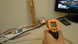
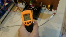
So, the whole machine gets biased up once I increace the current, It seems like as if all transitors are using equal biasing, including drivers, however it is just the single Q6 that seems to be slightly hotter than q8, as I can measure with a temp gun approximatly 1-2c diffrence in temps, but some how same temps once I fired it up for a long time and operated slightly pass the class a region 11 watts biasing.
Not transitors are overheating and they don't seem to be leaking
Not transitors are overheating and they don't seem to be leaking
If the temperature measurements are of the air rather than the body of the transistor in question the convention of air around Q6 might not be as good as for Q8. Are you happy with your amplifier now or do you have other unresolved concerns.
Last edited by a moderator:
I am actually happy, I am quite afraid to boost the current any further and its running great with 11watts of idle power. Extra 1watts on one side is no plorbem (My AMP meter had plorbems after I my MJ11033 popped and died on this amp, then I reverted back and decided to leave it here, the current wen't from 0.08amps to 1amps in 2 seconds while my protection bulp was on 😱)
Thanks for all the help guys 😀
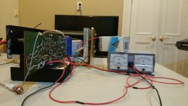
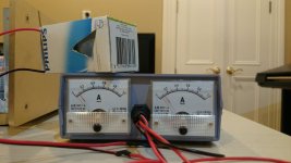
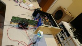
Here are some pictures of my amp, running in semi class a 😀 I uploaded these pictures to twitter so I can share with my friends, I am a bit lazy to upload the original pictures, so I just coppeied these off twitter. If you want to see some better quality pictures or more photos post a comment 😉
The picture seems like one side has 40ma more, but its actually 20ma, depends on which side you look at it
Thanks for all the help guys 😀
Here are some pictures of my amp, running in semi class a 😀 I uploaded these pictures to twitter so I can share with my friends, I am a bit lazy to upload the original pictures, so I just coppeied these off twitter. If you want to see some better quality pictures or more photos post a comment 😉
The picture seems like one side has 40ma more, but its actually 20ma, depends on which side you look at it
Attachments


Last edited:
Are those meters measuring total supply current rather than just the output stage device current ? If so then that would explain any imbalance. The current draw from each rail is never equal and would not be expected to be so.
Are those meters measuring total supply current rather than just the output stage device current ? If so then that would explain any imbalance. The current draw from each rail is never equal and would not be expected to be so.
Yeah, its the total, At first I was thinking the same too, but one pnp decvice is slightly hoter at the out puts(probally my temp meter isn't that accurate or it actually is using more), but nevermind, I decided to leave the current here and its working great. Further more the amp meter it self isn't that accurate
Temperature isn't a reliable guide. You can't guarantee the thermal coupling is the same between the two devices and you can't guarantee that the heatsink dissipates it heat equally per unit of surface area due to external factors.
I see, so whats the best way to do it? Is it having amp meters monitoring how much current the single transtior decvices npn and pnp draw?
I see, so whats the best way to do it? Is it having amp meters monitoring how much current the single transtior decvices npn and pnp draw?
You would normally measure the voltage drop across the power transistors emitter resistors and apply Ohms law to deduce the current.
The question here is whether or not you have fitted any. Otherwise fit 100R resistors in the power transistor collectors and measure the voltage drop across these.
Ah I see, guess I have to have some 5-10 watts resitors for the job which I don't.
Thanks for the info 😀
Thanks for the info 😀
1r0 passing 20mA will drop 20mV
You can easily measure 20.0mVdc on the 199.9mVdc scale of a cheap DMM.
1r0 passing 20mA will dissipate 400µW (=0.0004W)
Use any 1/8th W, or higher, resistor.
1r0 passing 300mAdc, or 300mAac, will dissipate 90mW, just within the capability of a 1/8th W resistor.
You can easily measure 20.0mVdc on the 199.9mVdc scale of a cheap DMM.
1r0 passing 20mA will dissipate 400µW (=0.0004W)
Use any 1/8th W, or higher, resistor.
1r0 passing 300mAdc, or 300mAac, will dissipate 90mW, just within the capability of a 1/8th W resistor.
1r0 passing 20mA will drop 20mV
You can easily measure 20.0mVdc on the 199.9mVdc scale of a cheap DMM.
1r0 passing 20mA will dissipate 400µW (=0.0004W)
Use any 1/8th W, or higher, resistor.
1r0 passing 300mAdc, or 300mAac, will dissipate 90mW, just within the capability of a 1/8th W resistor.
Ah, so I don't actually need high wattage reistors thanks for the info
- Status
- Not open for further replies.
- Home
- Amplifiers
- Solid State
- Help With My Class AB Biasing, Unbalanced npn, pnp current