I can't go through drawing all that ....... 30-th time .........
believe it or not , and search
having electrical short circuit through toroidal xformer isn't a wise thing .
magnetic properties of screw material doesn't have anything with exact problem
just iimagine piece of wire , made of base plate +left screw+Al plate +right screw+base plate again ;
isn't that short circuit , going through (any & both ) toroid ?
Last edited:
and stacking toroids would do the same ?
this means that two toroids shouldnt even be close to each other ?
but spreading them would cause issues as well ?
well, I have always preferred seperate monos anyway 😛
and 'lifting' the toroids with very thick rubbers
and using non metal top plate
this means that two toroids shouldnt even be close to each other ?
but spreading them would cause issues as well ?
well, I have always preferred seperate monos anyway 😛
and 'lifting' the toroids with very thick rubbers
and using non metal top plate
boys
be serious when serious things are in question
you can stack 2 or zillion of them , that don''t have anything with electrically short circuit , which is main issue here ..
just imagine properly mounted toroid in case : screw from bottom plate , going through toroid center , then small top plate (rubber plates I'm not counting this time ) .
then use your green-yellow wire , connected to one point of chassis already , and connect it to top of toroid's screw
what's happening ?
OK, let's solve it in simple way. The additional plate is unnecessary. Throw it away and bolt rectifiers on bottom plate.
Idiot just saws plate in two, as in circus.
(bigger idiot stacks toroids, then makes conductive circle for even prettier fireworks)
Fat mounting plate with thin ground wires is cool.
(bigger idiot stacks toroids, then makes conductive circle for even prettier fireworks)
Fat mounting plate with thin ground wires is cool.
Last edited:
Idiot just saws plate in two, as in circus.
(bigger idiot stacks toroids, then makes conductive circle for even prettier fireworks)
Fat mounting plate with thin ground wires is cool.
A person sees themself by projecting their personality onto others, and then watches the reflection come back.
.
naah
everyone knows that Jacco is always writin' looking at mirror
that's the reason why his posts you always must read through thick and pink glasses

everyone knows that Jacco is always writin' looking at mirror
that's the reason why his posts you always must read through thick and pink glasses
Gentlemen,
Thanks for pointing out a Shorted Turn.
Is this the problem ?
Shorted Turn - is a closed loop around a magnetic field, which can get a massive current induced into it 😱
Can a magnetic field induce a current in aluminum and stainless steel ?
However, could the magnetic field induce a current in the ferrous washers - which would then be conducted by the aluminum loop ?
To be on the safe side - I should break the loop.
Mounting diode bridges on top of the donuts is a technique I've seen on a few amps (with a single donut).
.
Last edited:
Do they conduct electricity ? 😉... Can a magnetic field induce a current in aluminum and stainless steel ?...
Underhill
Hot glue you mention is not the best way to secure those caps. I have done this before and overtime they can knock off easily. This side of mounting brackets pure silicone is superior every time to any type of hot glue sticks
Regards
David
Hot glue you mention is not the best way to secure those caps. I have done this before and overtime they can knock off easily. This side of mounting brackets pure silicone is superior every time to any type of hot glue sticks
Regards
David
Underhill
Hot glue you mention is not the best way to secure those caps. I have done this before and overtime they can knock off easily. This side of mounting brackets pure silicone is superior every time to any type of hot glue sticks
Regards
David
David,
Again - I stole the idea of gluing the electrolitcs down with hot glue
and wiring them P to P from a Blue Circle BC 1022 power amp.
The BC1022 An Exceptional Solid State Stereo Power Amplifier New Sounds Audio
The case and electrolytics were cleaned with alcohol (not beer) and the bond is so strong now,
I don't want to risk trying to pull them off.
In hind site - think I would have used water based contact cement.
P to P wiring of the electrolytics is a good technique.
However, its important there is good metal to metal contact before the solder is applied.
Bridging conductors with solder is not good.
However - I suspect soldering probably needs to be fast before too much heat damages the caps.
BTW: I used Cardas Quad solder - which has lead in it - yuk - but it flows quickly.
.
.
.
Before I get anymore Hazing - 2 corrections
1) The Bandwidth of the F5 is around 800 KHz - not 800MHz
2) In the F5 Turbo tutorial - N.P. did not write that he paralleled up Q1 and Q2 - my mistake
.
1) The Bandwidth of the F5 is around 800 KHz - not 800MHz
2) In the F5 Turbo tutorial - N.P. did not write that he paralleled up Q1 and Q2 - my mistake
.
Juma was right.
When the 0R1 source resistors were removed - and replaced with 0R47, the F5 became thermally stable.
Its very well behaved now.
Unfortunately - biased at only 0.5 Amps - and there is about 40 mVpp ripple on each supply rail.
Very disappointing - I thought only women could break my heart.
This is a new power supply - will it improve if the electrolytics break in ?
.
Attachments
Last edited:
first tell us just one thing :
check with ohmmeter do you have electrical contact between base plate of PSU and that upper Al plate ?
I know that I'm boring , but - as long is there possibility that you have starved PSU , there is no point in any sonic evaluation
check with ohmmeter do you have electrical contact between base plate of PSU and that upper Al plate ?
I know that I'm boring , but - as long is there possibility that you have starved PSU , there is no point in any sonic evaluation
check with ohmmeter do you have electrical contact between base plate of PSU and that upper Al plate ?
Yes. the resistance between the case and the plate was 0.
As a short term solution - I removed one of the bolts.
Long term solution - probably make a single plate for each donut.
.
Last edited:
good
double input Jfets , halve source resistors , halve feedback resistors , crank bias
then listen
double input Jfets , halve source resistors , halve feedback resistors , crank bias
then listen
closed loop around a magnetic field, which can get a massive current induced into it.
In your case less a tragedy, the magnetic vector of both cores are not in phase (for same side up).
Turn other toroid around, and you is in Doo-Doo.
(me always talk in first-person narrative, similar to "We, the King", but in my case "I, the Idiot")
Last edited:
good - double input Jfets , halve source resistors , halve feedback resistors , crank bias
then listen
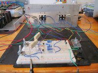
Here is my test set up
H/K 7600 CD player ==> Musical Fidelity v3 tube buffer ==> F5 Amp ===> scope & 10" Tannoy
changing one variable at a time
1) paralleling up the input jFET's increased the bass, dynamics and the music moved more forward.
Unquestionably, this mod is a keeper with the Gamut style MOSFET's.
2) The source resistors are presently 0R51 - I don't have 0R22's.
But from previous tinkering, I know there will be more bass if this value is lowered.
3) The 4 F.B. resistors were always 50 = R5 // R6 and 50 = R7 // R8
4) I moved the bias up to 1.3 Amps - I think it sounded more alive ???
Notes
When the bias was increased to 1.3 Amps - the ripple on the supply rails increased to 90 mVpp - not good
The amp is very thermally stable - when I switch it on, the voltage drop across the 0R51 source resistor is about 0.64 v
1/2 an hour later its 0.70 v
Switching on and off the F5 is very well behaved - no thump - no output hitting the voltage rails.
No output relay required.
92,000uF per channel should throw a 10" Tannoy around like there is no tomorrow.
But there is no bass.
.
Last edited:
In your case less a tragedy, the magnetic vector of both cores are not in phase (for same side up).
Turn other toroid around, and you is in Doo-Doo.
(me always talk in first-person narrative, similar to "We, the King", but in my case "I, the Idiot")
Yes your Magisty.
.
when I wrote halve source resistors I meant on input Jfet's resistors
that way you'll keep right current through all input jfets , and better drive of outputs
also - to keep CLG in ballpark , that's why I wrote to halve feedback resistors too
that way you'll keep right current through all input jfets , and better drive of outputs
also - to keep CLG in ballpark , that's why I wrote to halve feedback resistors too
- Home
- Amplifiers
- Pass Labs
- Help with F5 with Gamut style MOSFET's