Perhaps I should measure it from the underside, pcb side to exclude cold solder joint. Your suggestion is noninvasive, if I understand correctly one side of every resistor should read 0.0V relative to ground, main ground that would be E14?
What I would consider to be a main ground would be back in the power supply, preferably the transformer center tap.
Mike
mkusan,
1)Did you use MP3 player on battery while testing?
2)you said when no music is played, still some dc appears at the output. well, then was any player like CD or VCD player that runs on mains supply was connected to AMP's input? ( I wish to ask if the ground of other player that operated on mains supply was connected to the ground of this AMP?)
3) did you try physically disconnecting all inputs to the AMP?
4) also try connecting 4.7k resi at the input and ground. for both the channels. and on selector switch select the input where resistor is connected. but with no other device connected.
mkusan,
1)Did you use MP3 player on battery while testing?
2)you said when no music is played, still some dc appears at the output. well, then was any player like CD or VCD player that runs on mains supply was connected to AMP's input? ( I wish to ask if the ground of other player that operated on mains supply was connected to the ground of this AMP?)
3) did you try physically disconnecting all inputs to the AMP?
4) also try connecting 4.7k resi at the input and ground. for both the channels. and on selector switch select the input where resistor is connected. but with no other device connected.
1)Yes
2)No, it was easier for me to do tests with mp3 player, but I can try with standalone CD unit
3)Yes
4)Will try and post back
One more question for everyone, since there will be a lot of measuring tonight, can I use dim light bulb tester while measuring to minimize my chances of screwing something up or that will render the data useless.
Thanks
Marko
Bulb tester should be OK as long as the stabilised rails don't drop out (35 volt rail to preamp and the supply to the opamp). Better to have no speakers connected too.
Very difficult working from pdf's on screen.
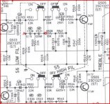
Measure on DC volts between these two points with the filter switch ON which places the caps in circuit.
Also measure DC voltage from ground to these two points which should also be zero.
Conducted the test with 75W in bulb tester:
across resistors started 2.3mV but dropped after 3 minutes to 1.5mV
from ground to R537 1.4mV to 1.1 after 3 minutes
from ground to R531 3.1 dropped to 2.8 after 3 minutes
Mora data will follow
Look at this. The filter switch is now in the "on" position.
The two voltages shown must be zero with respect to ground and zero volts between them.
The two caps marked "Check" if fitted back to front or faulty could cause a DC fault.
I checked C517 and C527, I haven't reversed polarity according to the minus sign on the board and to the photographs of old caps I took before recapping. In circuit capacitance value gives me 4.6uF for C517 and 0.9uF for C527.
The VU meters are driven from the main speaker output via an opamp and rectifier. It's all AC coupled so the only way the meters can deflect is either because of a problem around the opamp stage or because the amp really is actually oscillating and is unstable and there really is an unwanted AC signal present.
You mention in post #1 that the amp has had quite a bit of work done to it. All these problems perhaps suggest something that has gone amiss during all the mods rather than a genuine "one off" fault.
You are going to have to work on this one stage at a time and it would be useful to also check the stability with a scope, however if you remove C635 and C636 feeding the VU meter stage then the meters should show zero at all times. If they do not and still drift and show various readings then that confirms a problem with the VU stage.
If removing the caps does cause the meters to read zero again correctly at all times then that points to instability in the amp somewhere.
Removed C635 and C636 and the needles are zeroed in, moving of volume pot does not affect them anymore.
I agree that the resistors are the last to suspect. But the ground to the board being slightly bad, cold solder joint could possibly add a small potential and would account for the multiple symptoms as it is common to both the filtering and the bass control, also to both channels.
The image you posted was good but it is still hard to make out what is what and I assume by zooming out it will get harder to read. Measuring on the milivolt range of your meter using the main supply ground as your negative and the positive to the ground side of the resistors I mentioned see if you read anything. As Amptech pointed out it should be zero volts. Possibly during your first work you disturbed the connection and it started working, much like rocking a control back and forth to quiet it down. With time bad connections come back. Sometimes a can of freeze stray can help locate the culprit!
Mike
Mike, I think we made progress tonight🙄 hope so, at least.
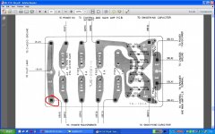
I was tired already but decided to follow your advice on resistors. I measured bunch of them from R539 to R546. Multiple resistors did not have absolute zero on one leg but R546 had 25V on one leg and 12V on the other, and touching that leg (I wore headphones) made a very unpleasant, loud buzzing noise in right channel, none of the other resistors made such noise while tested. R546 is a 330K third resistor from bottom of my picture resistor right to the suspicious one.
Mike, I think we made progress tonight🙄 hope so, at least.
I was tired already but decided to follow your advice on resistors. I measured bunch of them from R539 to R546. Multiple resistors did not have absolute zero on one leg but R546 had 25V on one leg and 12V on the other, and touching that leg (I wore headphones) made a very unpleasant, loud buzzing noise in right channel, none of the other resistors made such noise while tested. R546 is a 330K third resistor from bottom of my picture resistor right to the suspicious one.
From looking at the schematic that would be correct as it is connected between the supply and base of Q506. You are tired 😉. We are looking to verify that your ground to the circuit is actually ground, so the ground side of R29,30, 35, 36 should tell the tale. They should be zero and I'm just guessing but, I would think that at least 50mv or more would create the pop! If you don't see anything there with the meter ground to the centertap then it's a goose chase.
Mike
My "ground" in red circle.
Attachments
Conducted the test with 75W in bulb tester:
across resistors started 2.3mV but dropped after 3 minutes to 1.5mV
from ground to R537 1.4mV to 1.1 after 3 minutes
from ground to R531 3.1 dropped to 2.8 after 3 minutes
Mora data will follow
Those readings are good.
Does operating the low filter switch cause the noise you are complaining of while it is in this state ?
Polarity of caps seems OK. It can be marked wrongly sometimes on both PCB's and diagrams. 100% sure way to check is just to measure the DC volts across the caps in turn. Non should be reverse biased of course.
Removing C635/6 seems to show the meter problem is actually the meters responding to some AC signal that is present when it shouldn't be. So connect them back up again.
If the volume control makes a noise when turned and there is nothing connected to the input then it's worth checking that C505 and C506 are fitted correctly.
There should be zero volts DC on ALL legs of the volume control... check it.
Yes, but intensity of it decreases with time, after 10 minutes warming up time operating the low filter switch is barely noticeable.
Will check C505 and C506.
I already checked that before, if I remember correctly I had about 1.5mV on input and output legs. Will confirm exact numbers.
Lets just go over some of theory of whats going on as this is hard to diagnose without actually having the unit in front of me.
Due to the way the preamp output connects directly to the power amp input means that the slightest change in levels will be amplified and appear as a noise/thump etc.
Does that make sense... this is because the volume control operates before all the circuitry and so it can not reduce the level of any internally generated noise.
The voltage between these two points (which you measured) should ideally be zero). The small millivolt or so you measured from ground to these points could be down to the exact ground location you used and down to measurement/equipment error so just double check the reading between points A and B which should of course be zero.
If there is genuinely a slight voltage present then that would account for the noise on operting the switch. Without actually hearing it for real it's hard to determine if there is a real problem or not.
Remember that the slightest difference in voltage gets amplified by the preamp and power amp and that even an output across the speakers of just a few 10's of millivolts can sound quite loud. Could it e that the switch noise is within what would be considered normal ?
Something else you can try. If you remove C517 and C518 then that isolates the first preamp stage. All that would do is preclude the possiblity of anything before the switch causing a problem... it probably won't prove much but worh trying for curiosity.
The volume control should be silent when turned. As this is an AC coupled preamp I am wondering whether the control itself is noisy. Would that account for the noise in an AC coupled design ? It would have to vary the base current to the first transistor amp stage. As we are talking in such very small signal levels and currents then this could be a possibility (because any tiny changes are amplified by the preamp and power amp).
The only way to know for sure would be to try another pot but it would have to be done carefully as any connection issues would result in full output from the amp.
The volume control should have absolutely zero DC volts across it at all times.
Attachments
Lets just go over some of theory of whats going on as this is hard to diagnose without actually having the unit in front of me.
Due to the way the preamp output connects directly to the power amp input means that the slightest change in levels will be amplified and appear as a noise/thump etc.
Does that make sense... this is because the volume control operates before all the circuitry and so it can not reduce the level of any internally generated noise.
The voltage between these two points (which you measured) should ideally be zero). The small millivolt or so you measured from ground to these points could be down to the exact ground location you used and down to measurement/equipment error so just double check the reading between points A and B which should of course be zero.
If there is genuinely a slight voltage present then that would account for the noise on operting the switch. Without actually hearing it for real it's hard to determine if there is a real problem or not.
Remember that the slightest difference in voltage gets amplified by the preamp and power amp and that even an output across the speakers of just a few 10's of millivolts can sound quite loud. Could it e that the switch noise is within what would be considered normal ?
Something else you can try. If you remove C517 and C518 then that isolates the first preamp stage. All that would do is preclude the possiblity of anything before the switch causing a problem... it probably won't prove much but worh trying for curiosity.
The volume control should be silent when turned. As this is an AC coupled preamp I am wondering whether the control itself is noisy. Would that account for the noise in an AC coupled design ? It would have to vary the base current to the first transistor amp stage. As we are talking in such very small signal levels and currents then this could be a possibility (because any tiny changes are amplified by the preamp and power amp).
The only way to know for sure would be to try another pot but it would have to be done carefully as any connection issues would result in full output from the amp.
The volume control should have absolutely zero DC volts across it at all times.
Hi Mooly,
I think it would be best that I film what happens to woofer cones while pressing low filter button and i can record that scratchiness while turning the pot. Hell, I can live with noisy low filter, i don't even use it i like my controls flat. I only mentioned it because i thought scratchiness and popping were related. Remember scratchiness is there all the time while i move volume up or down, popping goes away with warm up time. I found my receipt for volume pot it dates 04/25/11.
TKD 2CP-601 100K dual log taper potentiometer Hifi Collective
The pot was silent all this time, I find it highly unlikely that it would last only eight months. We will come to the solution of this 😀
Does the volume control make the noise even with no inputs connected ? That is with no leads connected at all to the sockets.
It's a good quality pot and shouldn't cause an issue. The original on the circuit is shown as a 4 pin with a tapped feed for the loudness function although that won't alter the problem here.
Just to eliminate things what happens if you apply a short (solder a wire) between the end pins on each channel of the volume control. On the diagram that is between points marked 15 and 16 and ground.
Displaying a well known name on the label tells little about the quality.
The guarantee rules !
Many apparent manufacturers do not manufacture their own product. They pay some other company to make the product and/or components for them, with their label/logo on them.
The guarantee rules !
Many apparent manufacturers do not manufacture their own product. They pay some other company to make the product and/or components for them, with their label/logo on them.
My "ground" in red circle.
The black wire in the upper right corner of the PCB "to transformer" is the centertap and I would use it as the meter ground during troubleshooting. You might want to step back and look at all of your symptoms and look for a common thread between them.
Mike
Tale of resistors
R529 one side 1mV other 2.4mV
R530 one side 1mV other 17.3mV
R535 one side 3.4mV other 3.2mV
R536 one side 1mV other 17.3mV
Mike using yours test point as ground and with 75W bulb in dim tester this are the results.From looking at the schematic that would be correct as it is connected between the supply and base of Q506. You are tired 😉. We are looking to verify that your ground to the circuit is actually ground, so the ground side of R29,30, 35, 36 should tell the tale. They should be zero and I'm just guessing but, I would think that at least 50mv or more would create the pop! If you don't see anything there with the meter ground to the centertap then it's a goose chase.
Mike
R529 one side 1mV other 2.4mV
R530 one side 1mV other 17.3mV
R535 one side 3.4mV other 3.2mV
R536 one side 1mV other 17.3mV
Does the volume control make the noise even with no inputs connected ? That is with no leads connected at all to the sockets.
It's a good quality pot and shouldn't cause an issue. The original on the circuit is shown as a 4 pin with a tapped feed for the loudness function although that won't alter the problem here.
Just to eliminate things what happens if you apply a short (solder a wire) between the end pins on each channel of the volume control. On the diagram that is between points marked 15 and 16 and ground.
Hi Mooly, yes the volume pot makes the noise even with no inputs connected. I made a video of not so great quality, it is hard to see cones moving but at least you will understand what I mean by scratchiness. here is the link:
Rotel amp - YouTube
- Status
- Not open for further replies.
- Home
- Amplifiers
- Solid State
- Help with DC on volume pot