Readings due to normal effect of caps charging should stabilise within 60 seconds I would say. It's the last mv or two that take the time as it's an exponential function.
Your meter will be fine as long as it reads zero even if there is only a high value resistor across the leads (such as the 330k here).
Your meter will be fine as long as it reads zero even if there is only a high value resistor across the leads (such as the 330k here).
1. Remeasure and make sure 14mv or so is still present across R536
2. Now remove C518 and measure again. Is the the voltage zero or still 14mv ?
If you still can not get the reading as zero then there has to be some leakage somewhere or some contamination on the PCB that is conductive as we are left with just a resistor connected to ground.
Hi Mooly,
BIG 😀 update
1. Remeasured R536 14mV still there
2. Removed C518 4.7uF cap, now measuring 00.1mV
Kind regards
Marko
Hi Marko,
interesting result !
You have to now swap the cap to prove it's not that (or that it is). Any small value electroylitic (or film cap even) in the 1 to 10 uf range should do. Check the polarity too. If in doubt measure across the working cap on DC volts to determine polarity as board markings have been known to be incorrect.
If the 14mv is still there with another cap fitted then it's getting difficult without using a scope to see what is going on. It could be that the 14mv is caused by high frequency oscillation. That could tie in with the mystery of the volume control reponding to being touched etc.
Another thought on all this. The volume control is at the input to the whole amplifier. That means that the amp runs at "full gain" all the time as you have the preamp and power amp directly connected and so it is extremely sensitive to any noise etc that appears at the preamp input.
Normally a volume control is between preamp and power amp and so at normal volume levels any noises etc are attenuated... but not here.
Maybe the type of volume control is critical (meaning it's construction and shielding).
Try the cap first though.
You could also, if all that proves OK, remove C506 and connect the "left hand" end of C506 to ground. If you just leave it floating I suspect it would pick up a lot of noise and give a meaningless result. Use the correct preamp ground (bottom of R516).
Hi Marko,
interesting result !
You have to now swap the cap to prove it's not that (or that it is). Any small value electroylitic (or film cap even) in the 1 to 10 uf range should do. Check the polarity too. If in doubt measure across the working cap on DC volts to determine polarity as board markings have been known to be incorrect.
If the 14mv is still there with another cap fitted then it's getting difficult without using a scope to see what is going on. It could be that the 14mv is caused by high frequency oscillation. That could tie in with the mystery of the volume control reponding to being touched etc.
Another thought on all this. The volume control is at the input to the whole amplifier. That means that the amp runs at "full gain" all the time as you have the preamp and power amp directly connected and so it is extremely sensitive to any noise etc that appears at the preamp input.
Normally a volume control is between preamp and power amp and so at normal volume levels any noises etc are attenuated... but not here.
Maybe the type of volume control is critical (meaning it's construction and shielding).
Try the cap first though.
You could also, if all that proves OK, remove C506 and connect the "left hand" end of C506 to ground. If you just leave it floating I suspect it would pick up a lot of noise and give a meaningless result. Use the correct preamp ground (bottom of R516).
Hi Mooly,
unfortunately even after swapping the cap that dc is still there, I checked the polarity before and on a working cap after, no doubt here. Voltage measured across the cap is 13V.
In the absence of scope, I can build something like this audio probe if you think it would be worthwhile:
Debugging - DIY_Wiki
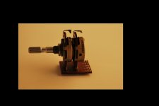
I took some pictures of the old pot, it is interesting that the old pot has only one post for earth, new tkd has two pins 1 and 2 , I put jumper across them.
Mooly, if you remember from one of my post early in this thread that when left powered on overnight vu-meter needles were closer to zero, doesn't that mean we are tracking thermally unstable component or cold solder joint instead of leaking caps, just a thought.
Regards
Marko
Attachments

Last edited:
I woudn't really say a probe like that is much use tbh
Did you try this with C506 as doing this removes the volume pot from the circuit and ties the input of the whole amplifier to ground. Use the correct ground as drawn.
If the voltage across the resistor was zero with C518 removed was zero (00.1mv) then it should be similar doing this test.
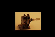
The original volume control. That "extra" tag at the top is a "tapped" connection (a fixed connection to the resistive track part way along it) for the "loudness" components to be wired to. It's something that's very rarely seen today.
You had better check you have wired the new one correctly. The wires to the tags on the old pot will have to be left disconnected and you will lose the loudness function. There's no way around that unless you use the correct pot.
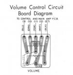
Look at the circuit... its the components to the left of the pot and connection J3 for the channel we are talking about.
I don't really think we are looking for a cold joint.
Transistor junctions can become thermally noisy but I don't think that is the problem here.
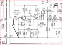
You have a small but definite voltage across that resistor. That voltage returns to zero when we isolate it from the first stage of the preamp (by removing C518). So we have to prove where that voltage is coming from. By grounding the input to the preamp as shown here we should be able to prove whether the voltage is caused by that first stage or by "something" causing that first stage to generate an AC voltage that is passed to the whole amplifier. It can not be a DC fault because the caps provide DC blocking and we have proved the stage around R536 to be OK. An AC fault would account for the VU meters registering too.
Did you try this with C506 as doing this removes the volume pot from the circuit and ties the input of the whole amplifier to ground. Use the correct ground as drawn.
If the voltage across the resistor was zero with C518 removed was zero (00.1mv) then it should be similar doing this test.
The original volume control. That "extra" tag at the top is a "tapped" connection (a fixed connection to the resistive track part way along it) for the "loudness" components to be wired to. It's something that's very rarely seen today.
You had better check you have wired the new one correctly. The wires to the tags on the old pot will have to be left disconnected and you will lose the loudness function. There's no way around that unless you use the correct pot.
Look at the circuit... its the components to the left of the pot and connection J3 for the channel we are talking about.
I don't really think we are looking for a cold joint.
Transistor junctions can become thermally noisy but I don't think that is the problem here.
You have a small but definite voltage across that resistor. That voltage returns to zero when we isolate it from the first stage of the preamp (by removing C518). So we have to prove where that voltage is coming from. By grounding the input to the preamp as shown here we should be able to prove whether the voltage is caused by that first stage or by "something" causing that first stage to generate an AC voltage that is passed to the whole amplifier. It can not be a DC fault because the caps provide DC blocking and we have proved the stage around R536 to be OK. An AC fault would account for the VU meters registering too.
No probe then, there is a definite chance of me laying a hand on an old Grundig oscilloscope sometimes next week 😀, which may be a good news or a bad one considering I never worked on one.
I did not try with C506 as my spirit was down after C518 was a no go. Will try tonight per your precise drawing and get back with the results.
The original volume control. Loudness wires were desoldered from the PCB while I installed new pot, I knew I will loose loudness function when buying new pot and it was of no concern to me. I checked wiring to and from the pot, no probs there.
I was just implying that there was a problem before recap, while the amp was still "virgo intacta" to the soldering iron , and the after vol. pot change, and after the transistors change in preamplifier. It seems to me we are chasing a problem which originates before my workings on amp and is probably related to amp age.
I dug some pictures I took before recapping, maybe they will be of some help.
Thanks for help Mooly
Attachments
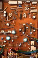
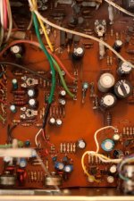
I can see it's quite an oldie just looking at the pics... older than I thought actually.
Lets see what the next test reveals anyhow.
Are those tantalum caps I see in the pic (lower left second pic) ?
Lets see what the next test reveals anyhow.
Are those tantalum caps I see in the pic (lower left second pic) ?
Lets see what the next test reveals anyhow.
Are those tantalum caps I see in the pic (lower left second pic) ?
Mooly, I think I am beginning to understand your wisdom in isolating the source of this problem. I did as you said, I removed C506 and used ground via R516. This time I am getting a reading across R536 9.3mV and I noticed the right channel VU-meter needle is closer to zero.
Those were tantalums, you are right, they were my suspects too. In the first post I wrote "changed C545,C546 tantalums 3,3uf to electros".
We are getting closer, I can feel it😉.
I would have expected a closer to zero reading tbh with the cap grounded.
This is where an oscilloscope makes it so much easier as you can see what is happening.
The VU meter reading closer to zero seems to prove that we have an AC problem/oscillation/instability of some kind.
Have the three caps C506/514/516 been replaced ? It's not unheard of for small caps like C508/510/512 to do strange things. The only way to prove that is to check by substitution. Anything from 33 to 68pf would do for the 30pf caps and 220 to 470 pf for the 300 pf one.
You are absolutely sure you connected the cap in previous post as shown 🙂 (just with you saying "I removed C506 and used ground via R516"). The cap has to be in circuit and is used to AC couple the input to ground 🙂
I would have expected a closer to zero reading tbh with the cap grounded.
This is where an oscilloscope makes it so much easier as you can see what is happening.
The VU meter reading closer to zero seems to prove that we have an AC problem/oscillation/instability of some kind.
Have the three caps C506/514/516 been replaced ? It's not unheard of for small caps like C508/510/512 to do strange things. The only way to prove that is to check by substitution. Anything from 33 to 68pf would do for the 30pf caps and 220 to 470 pf for the 300 pf one.
You are absolutely sure you connected the cap in previous post as shown 🙂 (just with you saying "I removed C506 and used ground via R516"). The cap has to be in circuit and is used to AC couple the input to ground 🙂
The picture below would probably explain unexpected result 😱
We will have oscilloscope next week, if you wish we can wait until then.
C506/514/516 have been replaced. C508/510/512 are ceramics, haven't changed them.
Attachments
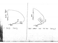
Yes, I want you to do that 🙂
Without the cap and just connecting R514 to ground will upset all the DC biasing of that first stage.
The cap "shorts out" any AC that might be picked up from having the input left floating.
Ceramic caps are prone to failure going noisy and leaky. Can be hard tp prove without just replacing them.
Without the cap and just connecting R514 to ground will upset all the DC biasing of that first stage.
The cap "shorts out" any AC that might be picked up from having the input left floating.
Ceramic caps are prone to failure going noisy and leaky. Can be hard tp prove without just replacing them.
Ceramic caps are prone to failure going noisy and leaky. Can be hard tp prove without just replacing them.
We will replace them then. I have 220pF polyester film and 330pF multilayer ceramic for that 300pF, what do you think is better substitute? I have nothing in 33 to 68pf value, will have to buy something.
Regards
Marko
Before you do that, try the cap test above first to see if that helps locate where the problem is.
The ceramic caps need to be replaced with something pretty close to the original values for a permanent swap (they determine the stability and HF characteristics of the two transistor voltage amplifier) but for testing they can be swapped one at a time with something close enough.
If you do swap permanently for new caps then,
330pf is OK for the 300pf as a permanent swap.
47pf for the 50pf
27 or 33pf for the 30pf
Poly or film is best, certainly for the 300pf, and for the 50 and 30pf either ceramic or film. Ceramics have a "bad" reputation for audio, not always deserved really with modern parts, particularly for very small value caps. Small film caps can be surprisingly expensive too.
Before you do that, try the cap test above first to see if that helps locate where the problem is.
Hi Mooly,
Tried the cap test, this time the right way not my way, now measuring 21.5mV across R536. That is not the result we were hoping for 🙁. Does that result tells us the problem is not in the first stage of preamp?
Thanks
Marko
Marko,
I'm just wondering the what make, type, value and rating of electrolytic caps you used to recap the power amp.
I have a feeling you used ones with high DC leakage. The original parts shown on the schematic are specified as LN with orange body, i.e."low noise" which are likely low leakage type
You should also put back the tantalum capacitors you removed. The electrolytic tantalum capacitors generally have 50-60x less leakage current than aluminum electrolytic capacitors.
Hi Mooly,
Tried the cap test, this time the right way not my way, now measuring 21.5mV across R536. That is not the result we were hoping for 🙁. Does that result tells us the problem is not in the first stage of preamp?
Thanks
Marko
An interesting result for sure. You really do need to scope this to see what is happening so if you can get hold of one...
What we have done by grounding the input stage via the cap is put the amp in the lowest possible "signal condition". If the cap was wired correctly it has removed the volume control and anything on the input side completely from the circuit. The amp has zero input applied.
The fact that there is still a reading across the resistor implies that the first stage of the amp is unstable or noisy in some way. By removing C518 the voltage (and VU meter reading) drops. All these tests are showing that the first stage is generating the problem.
Marko,
I'm just wondering the what make, type, value and rating of electrolytic caps you used to recap the power amp.
I have a feeling you used ones with high DC leakage. The original parts shown on the schematic are specified as LN with orange body, i.e."low noise" which are likely low leakage type
You should also put back the tantalum capacitors you removed. The electrolytic tantalum capacitors generally have 50-60x less leakage current than aluminum electrolytic capacitors.
It's true that tantalums were often chosen for low leakage years ago. Modern electroylitics are very much improved though... it's an interesting thought non the less.
Are they a reputable brand you fitted ?
You also replaced the transistors I think you said ? Could it be a noisy/faulty transistor perhaps. What type number did you fit ? This is where a scope check should help reveal the problem. It could even be some form of HF instability.
Question... when the VU meter is showing a reading and without touching anything (switches/volume etc) can you hear anything from the speaker ?
Marko,
I'm just wondering the what make, type, value and rating of electrolytic caps you used to recap the power amp.
I have a feeling you used ones with high DC leakage. The original parts shown on the schematic are specified as LN with orange body, i.e."low noise" which are likely low leakage type
You should also put back the tantalum capacitors you removed. The electrolytic tantalum capacitors generally have 50-60x less leakage current than aluminum electrolytic capacitors.
Hi hitachi_nut,
I chose LN substitutes very carefully, I used Elnas low leakage series RLB for 1uF. I don't remember originals to be orange though, I think they were blue brand Taicon. For higher values LN caps I used FG Nichicon type.
Last edited:
An interesting result for sure. You really do need to scope this to see what is happening so if you can get hold of one...
It's true that tantalums were often chosen for low leakage years ago. Modern electroylitics are very much improved though... it's an interesting thought non the less.
Are they a reputable brand you fitted ?
You also replaced the transistors I think you said ? Could it be a noisy/faulty transistor perhaps. What type number did you fit ? This is where a scope check should help reveal the problem. It could even be some form of HF instability.
Question... when the VU meter is showing a reading and without touching anything (switches/volume etc) can you hear anything from the speaker ?
Hi Mooly,
I will get a scope in the next week or so, it is a loan from a colleague who works with hearing aid apparatus. Lets just hope it will be suitable for our application.
Those tanatalums were replaced with 3.3uF 50V Elna Cerafine.
I replaced transistors with SC2240GR.
Without touching anything the only sound I hear is a sound of silence (by Simon & Garfunkel)😀. No, I cannot hear anything.
Any analogue scope with at least 10Mhz bandwidth and a sensitivity of 1 to 5 mv/div should be useful (which covers just about any traditional scope made in last 50 years 🙂).
Only silence and yet the VU meter registers... that points to some form of HF instability. If I remember correctly we proved the VU meter OK by disconnecting its input and it then showed zero.
Only silence and yet the VU meter registers... that points to some form of HF instability. If I remember correctly we proved the VU meter OK by disconnecting its input and it then showed zero.
- Status
- Not open for further replies.
- Home
- Amplifiers
- Solid State
- Help with DC on volume pot